DRV8952: Designing with DRV8952

Part Number: DRV8952

Tool/software:

Hello Team,
We have a system that uses the motor driver DRV8952DDWR.
OUT1 & OUT2 forms and H Bridge and OUT3 & OUT4 forms the second H Bridge.
We are using 2*24V DC motor.
The DC Motor will be in a test jig
We have a relay board between the driver board and the DC Motor
The relay board help to connect/test different driver boards with the same motor.
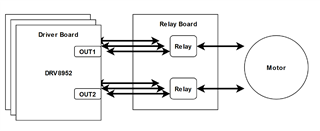
The relays will be closed all the time and thus we get a the expected behavior.

Can you please clarify the following doubts we re having.

1). If a driver board is controlling the motor and the motor is rotating in a direction and if we switch the motor to some other driver board with the relay without giving any time to freewheel, will this damage the 2nd driver IC?.

2). If this damages the IC, can we use a bidirectional TVS diode across the motor to dampen the back EMF?.

3). All driver boards are independently powered and have their own MCU and software. Which means the driver will be configured to rotate in forward or reverse direction while switching with the relay. Will this create any problem?.

Looking for your reply

  • Hello Team,
    Any updates on this?

  • Hello,

    Thanks for your question. My team mate will look into this and get back to you.

    Thanks,

    Ibinu

  • Hi Sv,

    In theory, it sounds like this should not be an issue. However it is recommended to evaluate designs with an EVM to be sure. The timing of each driver with independent software could make things tricky. Due to the inductance of the motor, without giving the motor time to freewheel the current during switching periods, can lead to reduced efficiency and electrical stress on the motor. How often do you plan to switch the motor direction?

    https://www.ti.com/tool/DRV8962EVM 

    Are you implementing Independent 1/2-bridge control or PWM?

    The device automatically handles the dead time generation (typically 300ns) when switching between the high-side and
    low-side MOSFET of a half-bridge. 

    If the motor is continuing to spin when switching to another driver, it would be recommended to use transient protection like a bi-directional TVS diode.

    Best,

    David

  • Hello David,
    Thank you for your reply.

    Are you implementing Independent 1/2-bridge control or PWM?

    We will be implementing an H Bridge using 2* 1/2 bridges.

    How often do you plan to switch the motor direction?

    Not so frequently.
    It is like, the motor will be rotating in one direction, and then to opposite direction based on the software and then switch to another driver circuit. or like, the motor will be running in one direction, then switch to another driver board.

    it would be recommended to use transient protection like a bi-directional TVS diode.

    Did you mean putting a TVS diode across the motor lines?.
    The motor is rated for 24V.
    What should be the clamping voltage of the TVS diode?

    Can you please answer my following queries.

    1). What will happen to a motor or its driving circuit if we don't have a free wheeling path?.
    2). What will happen to a motor or its driving circuit if we disconnect the motor lines when it is working?.
    3).

    However it is recommended to evaluate designs with an EVM to be sure. The timing of each driver with independent software could make things tricky

    If we only have a single driver board and the relay board can make and break the connection, the relay disconnects the motor from the driver when the motor is working, then the driver is switching the polarity (not knowing the disconnection of the motor through the relay), and then the relay connects again.
    Since the motor is charged and the driver changed the polarity, what will happen to the driver??.

    Looking for your reply

  • Hi Sv,

    Typically, TVS diodes are placed on the switching node (output pins) and should be rated the same as the supply voltage. 

    1). What will happen to a motor or its driving circuit if we don't have a freewheeling path?

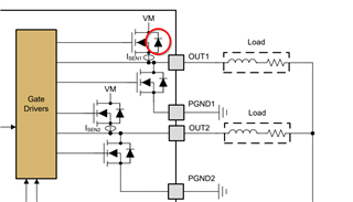
    - All TI motor drivers, including DRV8952, have integrated freewheeling diodes across each FET. A brushed-DC motor has inductive properties and current through an inductor cannot change instantaneously. As the voltage across the motor changes, these diodes provide a safe path for current to recirculate. 

    2). What will happen to a motor or its driving circuit if we disconnect the motor lines when it is working?

    - This device doesn't support open load detection. Disconnecting the motor would likely put the outputs into a high-Z state. 

    3). Since the motor is charged and the driver changed the polarity, what will happen to the driver?

    - If the motor voltage is higher than the supply voltage (VM) it can cause current to flow back to the supply. This is sometimes called VM pumping and more information can be found below.

    7701.The art of stopping a motor.pdf

    Best,

    David