This thread has been locked.

If you have a related question, please click the "Ask a related question" button in the top right corner. The newly created question will be automatically linked to this question.

The motor has a loud noise and the driving current is not a sine wave

Part Number: DRV8889-Q1

Tool/software:

Hi:

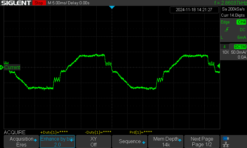
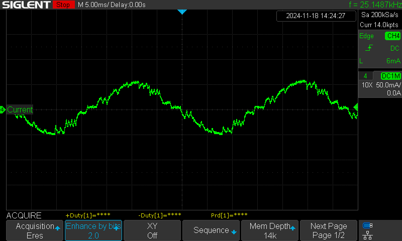
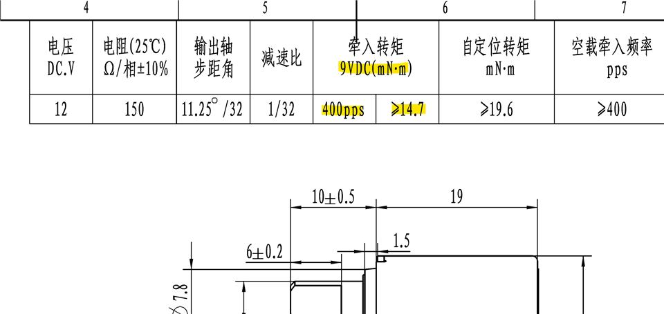
We use 8889A to drive the motor, configured for 1/4 micro step, Smart tune Ripple Control mode, providing 480 pulses per second on the STEP pin, and the motor noise is very loud. We also tried other PPS and micro step parameters, but the motor noise did not significantly decrease. The motor supplier told us that the motor drive current cannot be reduced, otherwise the motor cannot be driven. How can we reduce motor noise and make the motor drive waveform approach a sine wave.
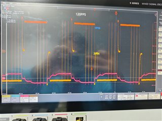
 Q24BYJ48-3361w.pdf

  • Hello,

    The device expert will review the question and get back to you.

    Thanks,

    Ibinu

  • Hi,

    Thanks for sharing the current waveform and the stepper motor datasheet. According to the datasheet the motor DCR is 150 Ω. What was the VM power supply used for driving this motor? Assuming it is 12 V the maximum steady state current through the winding would be VM / DCR = 12/ 1500 = 80 mA. This is a very low IFS full-scale current.

    What was the target current set with VREF for driving this motor? For proper current regulation and wave shaping it must be set < 80 mA, a good target would be around 60 mA. Anything higher would not allow proper current regulation because coil current would never reach ITRIP threshold and result in highly distorted current waveform. 

    See below current waveforms using our EVM and an example motor which is similar specs but a bit higher DCR 220 Ω, VM = 12 V, IFS = 80 mA, 1/4 step mode, 480 PPS on the step pin.

    IFS = 50 mA, rest of the settings identical to the above.

    Another downside of using such high DCR low current stepper motors is they are not suitable for stall detection because their back EMF is of very low amplitude. If you could identify a stepper with higher DCR and higher current it may be better suitable. For example the 20BYJ26 stepper. What is the end application? Thank you.

    Regards, Murugavel 

  • What was the target current set with VREF for driving this motor?

    Hi:

    Thank you for your help,Our initial parameters were VREF 1.65V,  TRQ 100% , Ifs 0.75A,  Component drive torque requirement 160gf.cm ,Our current driving parameter is VREF 1.65V. TRQ 6.25% ,IFS 47mA, Toff 7us. The motor noise has significantly decreased,and the waveform is also close to a sine wave . How can we estimate the motor torque?

  • Hi,

    Thanks. I'm glad we were able to address this issue. Please mark this post as RESOLVED.

    How can we estimate the motor torque?

    According to the motor datasheet you shared there is a specification for output torque at a certain speed. Typically this specification is for full-step mode and direct drive meaning the steady state current is V/R = 9/150 = 60 mA IFS. In full-step mode the current waveform would be close to a square wave. The output torque is proportional to the area under the current waveform, both positive and negative must be added with modulus. Using this approach find the area of the square wave with 60 mA amplitude and the STEP period width as well as with the sine wave area under the curve - see the second snippet. The ratio will give you the estimated output torque of the stepper. With sine wave current the motor will run quieter and cooler but the torque will be the maximum with the full-step square wave.  

    Regards, Murugavel 

  • Hi,

    Under 12V voltage conditions, the motor rotates faster.

    This is expected because higher IFS can be achieved with 12 V, 12 V1/50 Ω is > 9 V/150 Ω so torque is higher hence higher speeds can be achieved without stalling. With 9 V the target current may not be achieved if it is > 9 V/150 Ω. 

    Some vendors provide speed torque curves for current regulated bipolar drivers with specific VM voltages. There is also one more parameter some stepper vendors may provide but not common. A stepper motor torque constant, denoted as "Kt", is a value that represents the ratio between the torque produced by a stepper motor and the current flowing through its windings. Torque (T) = Kt * Current (I) .

    Regards, Murugavel