This thread has been locked.

If you have a related question, please click the "Ask a related question" button in the top right corner. The newly created question will be automatically linked to this question.

DRV8840: Current regulation does not work

Part Number: DRV8840

Tool/software:

Hi Forum,

i've used the DRV8840 in a recent design and cannot get it to work. I've tested two different boards, both were manufactured by a professional company so soldering is not an issue. 

I've used two different BDC motors as well as a ~2mH Inductor (magnet wire from the lab as a simple coil). 

Measuring the voltage over Rsens I get the following behaviour:
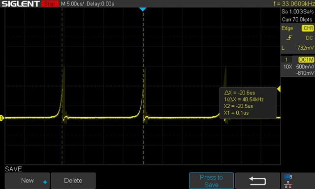
zoomed in:

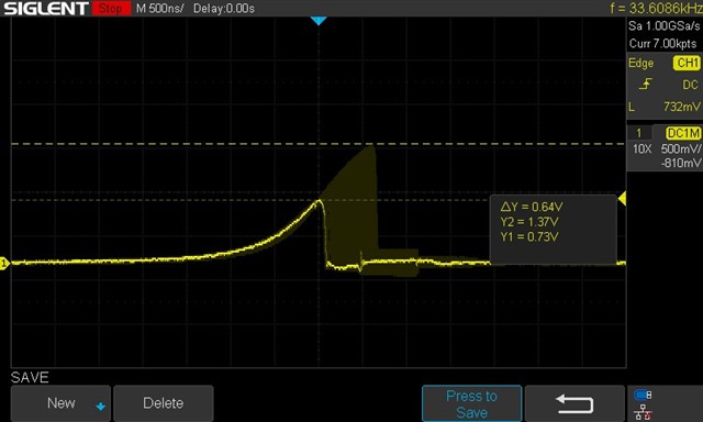
The yellow shadow is due to persistent turned on,.. the Voltage is all over the place and far from the set max current. Also, the current seem to drop down back to zero before the next cycle starts,... although the internal frequency of 50kHz can be measured.

I've tied the nSLEEP to 3.3V (external supply on the board). All other Pins are tied to 3V3 from the DRV LDO Out,... either via 10k or directly (checked both options,.. not working at all).

The schematic is the one from the board and has some features which i've removed for testing:

* the Diode in parallel to the motor is not placed

* the nSLEEP is no longer tied to the res array, but to the ext. 3V3 rail. 

* the EN pin is not actuatet with a PWM but with a constant 3V3 signal. 

* All Ixx pins are tied to the "3V3_driver" rail

* reference voltage, 3V3_driver has been measured correctly 


And the last thing: the layout. There are many vias and thin traces, but the motor was designed to run at 300mA,.. thus the layout is not that high power.

I have no clue at all on what is goin on here,.. did you have any sugestions? 

Thank you and kind regards,

Tony

  • Hi Tony,

    I would be happy to help you with this issue. 

    If possible, could you please provide me with scope captures of inputs and outputs? This would help to better understand the issue. 

    When you're driving the brushed-DC motor, does it spin? 

    Best,

    David

  • Hi David,

    I actually found out that during the tests with a pure inductor, the circuit seems to work fine. I just had a wrong assumption on how waveforms should look like. So the IC is doing its job fine. 
    I've checked the motors further and found out, that the input of both of those are measured capacitive with around 15µF... I think those motors feature an extremely high EMI cap inside which completely confuses the chopping circuitry. 

    I've requested more information about the motor from the provider to check, whether I can compensate that large of a cap by adding parallel capacitance over the R_sens. 

    Have you faced such an issue before? 

    Kind regards,

    Tony 

  • Hi Tony,

    Glad to hear that the device is working as expected. 

    If you can't use a motor with higher inductance, then using caps in parallel to the motor to reduce the capacitance sounds like a good idea. Please keep us updated on the testing and let us know if there are any other issues. 

    Best,

    David

  • Hi Tony,

    I'm glad to hear the device is working as expected. 

    If you can't use a motor with higher inductance, adding a cap in parallel to the motor to reduce capacitance sounds like it could work. 

    Please let us know how the testing goes, and if any other help is needed. 

    Best,

    David