Tool/software:
I want to ask how the DRV8353S internal current amplifier calibration works. What I have observed thus far, is that for a constant current through a shunt resistor, repeatedly power cycling my device produces 3 discrete "calibrated" values on the output. The process to find this is as follows:
- Make a special FW, which does not drive the gate driver inputs. The MCU just sets the PWM outputs to ground as standard GPIOs. This disables the MOSFET switching
- Solder a wire onto a test point on the phase-side of one of the shunt resistors, This bypasses the MOSFET of course, we are just driving current through the shunt resistor. There may be some current draw through the parasitic in the MOSFET however. Note the shunt resistor is 0.001R.
- Put a 110R load between the added wire and a bench power supply. Now using the bench supply ,we can put 20-40V to supply between 200 to 500mA current load through the shunt resistor.
- Put a scope probe on the output of the current sense amplifier
- The firmware configures the sense amplifier as:
- 20x gain
- Bipolar
- Choose a current; for this, I ended up using 220mA.
- Repeatedly power the device.
- Note that the current through the shunt resistor is left on during power cycles
- After each power cycle, take an averaged measurement of the current sense output.
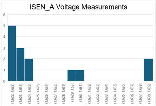
What I have observed is that with each power cycle, the measured amplified voltage outputs discrete values. In this case, it takes on either 1.610V, 1.636V, 1.623V. It will seemingly randomly move between these values with each power cycle. I cannot see where else in the system this behaviour might come from. So my question is then, what is the resolution of the amplifier calibration? Is it possible that with each power cycle, the offset re-calibration latches to discrete values that produce these small changes in the output? Note that the measured voltage is taking over a long period and averaged on a scope.
Unfortunately we are operating at the limits of what the hardware can do, so I am aware these are tiny differences in measurement! We are trying to eek out sensible measurements here, as they affect the behaviour of the system at near-zero current measurement.
Edit: Here are two histograms for the above tests.
The first shows the vanilla firmware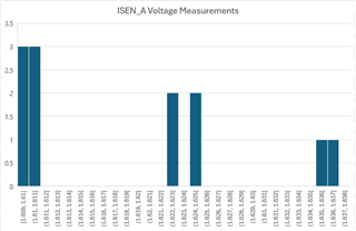
And this second one shows a change to the test FW, where the calibration of the current sense amplifier has been delayed by ~40ms power boot up to reduce effects of the device boot and power supplies coming up.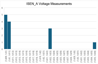
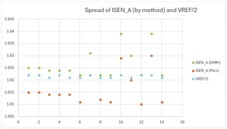
After this post I performed further measurements. The test FW disables the gate drivers, and there is no current through the shunt resistors. So the measured zero-current output of the amplifier should in theory be VREF/2. To confirm that the measurement method was not producing the discrete values, I performed the output measurement on both a digital multimeter, and a Picoscope on 14-bit resolution. There is a small offset between these two measurement methods, but this confirms that the measurement device is not the source. The below histogram shows the spread of amplifier outputs (ISEN_A) between power cycles. The plot below shows that VREF (the 3v3A power rail) is not the source, as it remains fairly stable even when output is doing this "latching" between different values on the output.