


Tool/software:
Hi TI,
I am using DRV8874 in one of my designs. I am using half bridge to control 2 motors. I am connecting the 2 motors on the high side and the driver is on the low side.
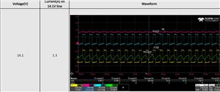
1)While capturing the waveforms, i have one issue with positive and negative current. Negative current peaks are high. Why there is a negative current? Is that a driver characteristic? PFA the screenshot of the waveforms. The waveforms are captured by connecting only one motor. Green is negative current. Current is probe on Out1.
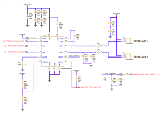
2) DRV8874: 6-A Peak: this is according to datasheet. Can it sink 6A peak continuously by each pin (6+6=12A) or 6A/2=3A?
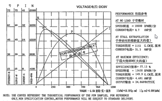
3) My motor requires 9V DC constant. Motor specs is attached. How to calculate the right PWM frequency so that my motor driver will be able to drive the load properly.
4) while increasing the Vm voltage, why the waveform is like this/ very distorted?
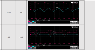
15.478,18.5 are the voltages applied. and adjacent is their currents.
Regards,
Ratan
