This thread has been locked.

If you have a related question, please click the "Ask a related question" button in the top right corner. The newly created question will be automatically linked to this question.

DRV8801-Q1: DRV8801QRTYRQ1 Failure during RF immunity testing.

Part Number: DRV8801-Q1


Tool/software:

Hello,

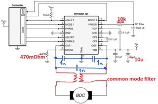
We are using DRV8801QRTYRQ1 in our current design - an actuator with a 12V BDC motor. The housing is made of plastic.

Power supply - 24V, PWM duty cycle - 50%. The length of the tracks from the driver to the MCU is about 40-50 mm. The sense resistor 470 mOhm, is placed close to the driver. In normal conditions, nFAULT is high even if the motor's shaft is blocked. 

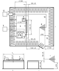
We conducted RF immunity test according to ISO 11452-2 (Absorber-lined shielded enclosure): 100MHz...2GHz, 100V/m.

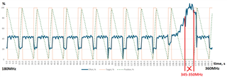
During the test, we faced motor stops at some frequencies, about ~340-350MHz and ~380MHz (it's difficult to define exactly). nFAULT signal goes low and the driver is shut down (it looks like overcurrent protection triggered). Temperature and input voltage were controlled during the test and did not go beyond normal values. What could be the problem and how can the design be improved in terms of RF immunity?

Best regards, 

Yauhen

  • Hi Yauhen,

    Thanks for your question.

    Do you have the waveforms of current through the coil and voltage on OUT nodes during the failure.

    Thanks,

    Ibinu 

  • Hi Ibinu,

    unfortunately, it is impossible to connect additional measuring equipment due to high interference levels. There is only information about motor current measured by MCU at VPROPI pin.

    The idea of the test: the actuator is lifting weight up and down between its 0% and 100% positions. Orange line - target position for the shaft (%). Green dotted line - current position (%). And blue line - motor effort (current, in %). When the green line goes up (from 0 to 100%) this means that the actuator is putting the weight down. That's why the path from 100% to 0% takes more time than backward.

    Every 1 second the test frequency increases. When the frequency reached 340-350MHz the measured current value began to increase and the motor stopped (you can see that the green line stuck at 0%). After frequency changes, the DUT continue to work normally.

    Thank you,

    Yauhen

  • Hi Yauhen,

    Are you able to add caps to the 0.1 nF to 100 nF near the output terminal to see if there is any change in behavior?

    Can you also try the same values for VBB?

    I am trying to understand how the RF noise couples to the board and what is transporting that noise. The capacitors should help in trying to filter that noise.

    Best,

    Keerthi

  • Hello Keerthi,

    Thank you for the response. 

    how the RF noise couples to the board and what is transporting that noise

    That's a good question.

    Yes, I plan to add 3x1nF capacitors close to the driver output terminals: between out+ and gnd, out- and gnd and between out+ and out-. I can add one 1nF to VBB as well. 

    By the way, we tried adding 100pF capacitors not close to the driver, but close to the motor terminals (between the terminals and the motor housing), but there was almost no effect.

    Do you have any other ideas about this? What else can be investigated during our next lab visit?

    Figure 1 - Green capacitors - the way we have already tested our device. No effect.

    Figure 2 - Blue capacitors - The configuration that is going to be tested during the next visit.

    Best regards,

    Yauhen

  • Hi Yauhen,

    Does changing the length of harness have any impact on what frequency the issue occurs at?

    Can you check without load to see if there is another path besides OUT?

    100 pF, 1 nF on VBB could also be some trials.

    Do you have a layout you can share?

    Best,

    Keerthi

  • Hi Keerthi, 

    Thank you for the reply.

    Does changing the length of harness have any impact on what frequency the issue occurs at?

    What harness do you mean: the long one for the power supply or the wires between the PCBA and the motor? In general, it is difficult to detect the exact frequency of the problem, since there is no feedback between test equipment and DUT. It is defined approximately by visual observation during the test and the post-test analysis so that the error can be up to 10MHz. We tested slightly different wires between the PCB and the motor, but it didn't seem to make a significant difference in the frequency.

    Can you check without load to see if there is another path besides OUT?

    Do you mean not using a load and letting the actuator move up and down without any load at all?

    What other methods of improving immunity are possible here, besides shielding and adding capacitors? Extra capacitors on VBB will be added.

    P.S. I'm not sure if I'm allowed to show the layout. 

    Thank you,

    Best regards,

    Yauhen

  • Hi Yahuen,

    Capacitors are the usual way I have seen, but I am asking around internally if anyone has any ideas.

    Best,

    Keerthi