This thread has been locked.

If you have a related question, please click the "Ask a related question" button in the top right corner. The newly created question will be automatically linked to this question.

MCF8329A: Question about I2C Communication Buffer Preparation Time

Part Number: MCF8329A

Tool/software:


Hello, I am currently developing with the MCF8329AQ1 and encountering an issue during I2C communication. Let me explain the situation step by step:

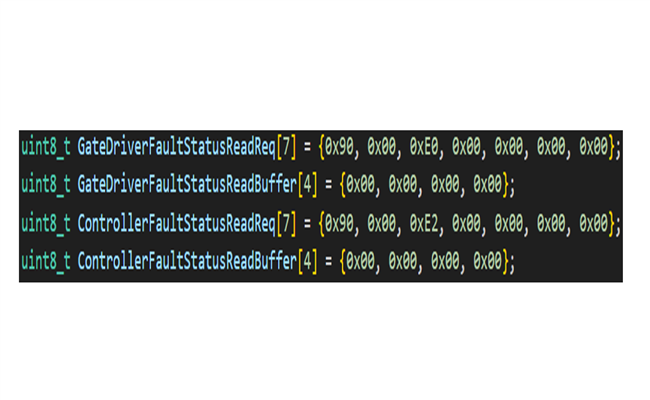
  1. To read the GATE_DRIVER_FAULT_STATUS register (0xE0), I created and sent the GateDriverFaultStatusReadReq buffer as shown in the attached image.
    (Task completes once)
  2. The response was received in the GateDriverFaultStatusReadBuffer.
    (Task completes once)
  3. To read the CONTROLLER_FAULT_STATUS register (0xE2), I created and sent the ControllerFaultStatusReadReq buffer as shown in the attached image.
    (Task completes once)
  4. The response was received in the ControllerFaultStatusReadBuffer.
    (Task completes once)
  5. For the ALGO_DEBUG1 register (0xEC), I parsed and wrote the target speed value and sent it.
    (Task completes once)

I implemented this process to run continuously in a 2ms task, but the I2C communication with the driver malfunctions intermittently. When enabling only one Read or Write operation at a time, adding a delay of approximately 1.1ms between communications allows for successful operation. However, when testing with multiple registers enabled simultaneously, the timing seems to vary.

I suspect that the issue may be caused by insufficient buffer preparation time. The datasheet lacks sufficient information about the internal buffers. I would like to understand the preparation time required for the internal buffer. Could you provide any relevant materials or explain this matter in detail?

Thank you.

  • Hi,

    Thanks for your question, we recommend around 15ms of delay between the I2C frames for a reliable communication.

    Thanks and regards,

    Sachin S

  • I have a question.

    Introducing a 15ms delay seems excessively long. Are you suggesting, as shown in the picture I attached, that I should configure a buffer, send a request, wait 15ms, and then perform a read?

    If so, should I also wait 15ms between the read and the next send when I want to read another register immediately after reading one? Let me describe the operation sequence for clarification:

    1. Send (Request)
    2. 15ms Delay
    3. Read (Buffer)
    4. 15ms Delay
    5. Send (Another Request)
    6. 15ms Delay
    7. Read (Buffer)
    8. ...

    If I follow this approach, reading 2–3 pieces of data would already take around 30ms. Is this the correct way to proceed?

    Also, I am performing a task to read the attached registers (0xE0, 0xE2) at once using a 64-bit option. In this case, should I wait 30ms instead of 15ms? And would the sequence need to follow this pattern:
    Send → 30ms Delay → Read → 30ms Delay → Send?

    I would appreciate your clarification.

  • Hi,

    Only for the device, a 15ms would be needed to take another command. For e.g:

    Send (request) --> wait 15ms ---> Send (another request).

    And while this is happening, you can store the received data in a FIFO? 

    Let me know if I understood your implementation correctly.

    I will get back to you with respect to the 64-bit option.

    Thanks and regards,

    Sachin S

  • Hello, thank you for your kind response.

    Based on what you mentioned, it seems that a 15ms delay is only required after completing the Receive operation and before accessing another register. How much delay should be given between sending the Receive Request and actually receiving the response? Currently, I am using a delay of about 5ms, but could you let me know the delay recommended by TI?

    Thank you.

  • Could you tell me what is the data rate for the I2C you are operating at?

    Thanks and regards,

    Sachin S

  • It's 100kHz

  • Okay,

    By "actually receiving the response", you mean receiving the full data bytes into your buffer right? If yes, this time should not be more than 2ms according to my calculations. But TI does not have a recommendation here, since it depends on the clock frequency at which you are operating.

    Correct me if my assumption is wrong.

    Thanks and regards,

    Sachin S

  • Thank you so much for your kind response.

    I set the interval between Request and Receive to approximately 2–5 ms and the interval between consecutive Requests to 15 ms, and the communication is now working well.

    However, I have one question: Is there a pin available to reset the entire system? For example, in a situation where the I2C of the driver becomes unresponsive, is there a way to control a specific pin to recover it?

  • Hi,

    Sachin is out of office until 2nd Jan. Let me add the comment here. For resetting the device, the device need to put into sleep by configuring the device in sleep and pulling down the SLEEP/WAKE pin. Other option is to power recycle.

    Regard,

    Manu