Because of the holidays, TI E2E™ design support forum responses will be delayed from Dec. 25 through Jan. 2. Thank you for your patience.

DRV8353: DRV8353 VDS and Vsense

Part Number: DRV8353

Tool/software:

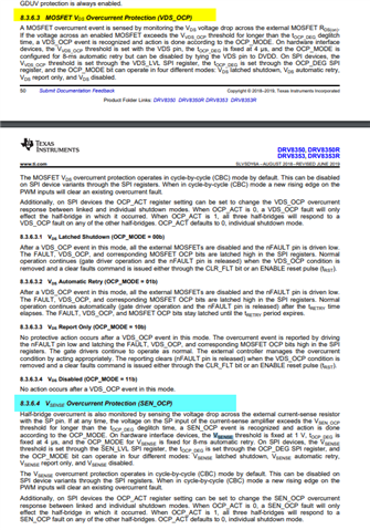
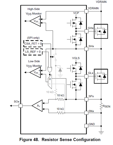
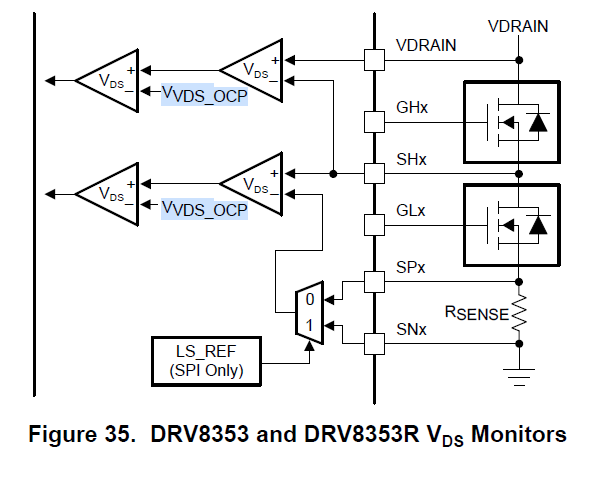
Based on Fault table 6, 8353 can be programmed to detect over current using both VDS and Vsense simultaneously but different paths in internal circuitry. Figure 48 shows VDS configuration using Rsense external power resistor use case. High side VDS is set to detect voltage across high side external FET which this diff voltage is compared to VDS_OCP threshold which is same for both hi and Lo sode fets. See both figures below.

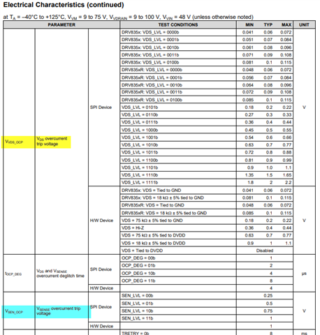
1. However Vsense overcurrent detection schematic showing measurement and threshold comparator for Vsense_ocp  threshold is not shown in the specs like VDS overcurrent options are shown. Can you help with this please.

2. If I want to use VDS detection for low side with external Rsense, then given VDS_ocp same for high and low fets, for an fixed value of over current I need to set CSA_FET =0 and LS_REF =0 so minus input of low side VDS monitor is tied to SPx other wise high and low sides will measure different resistors (low side fet R plus Rsense where high side only fet R). Is this correct. 

3. Given, I program CSA_FET and LS_REF both to 0, does this anyway effect which signal Vsense is monitoring; I expect Vsense and VDS are independent. Please let me know.

4. Given both VDS and Vsense overcurrent are tied to same OCP_MODE setting, is there a way to disable one and use the other such as use Vsense only with VDS disabled?
Regrads

TG

  • Hi TG,

    I'm looking over your questions today, I will need a couple of hours to provide an update.

    Regards,

    Yara

  • Hi TG,

    Apologies for the delay.

    1. However Vsense overcurrent detection schematic showing measurement and threshold comparator for Vsense_ocp  threshold is not shown in the specs like VDS overcurrent options are shown. Can you help with this please.

    I believe this is the spec you are looking for?

    2. If I want to use VDS detection for low side with external Rsense, then given VDS_ocp same for high and low fets, for an fixed value of over current I need to set CSA_FET =0 and LS_REF =0 so minus input of low side VDS monitor is tied to SPx other wise high and low sides will measure different resistors (low side fet R plus Rsense where high side only fet R). Is this correct.

    I'm a little confused by what you're asking here. Rsense is a current sense resistor that does in between the SPx and SNx pins. VDS monitors the voltage drop across the external MOSFET. For Vsense the voltage on SP pin is monitored. If the voltage on the SP input of the current-sense amplifier exceeds the VSEN_OCP threshold for longer than the tOCP_DEG deglitch time, a SEN_OCP event is recognized and action is done according to the OCP_MODE.

    3. Given, I program CSA_FET and LS_REF both to 0, does this anyway effect which signal Vsense is monitoring; I expect Vsense and VDS are independent. Please let me know.

    if you program both CSA_FET = 0 and LS_REF = 0, this configuration disables the MOSFET VDS sensing mode, and the current sense amplifiers will operate in their default shunt resistor-based current sensing mode. in this configuration, Vsense (which reflects the amplified signal from the shunt resistor) is entirely independent of VDS. The amplifiers do not monitor VDS when CSA_FET=0

    4. Given both VDS and Vsense overcurrent are tied to same OCP_MODE setting, is there a way to disable one and use the other such as use Vsense only with VDS disabled?

    VDS and Vsense are not tied to the same OCP settings

    Regards,

    Yara