This thread has been locked.

If you have a related question, please click the "Ask a related question" button in the top right corner. The newly created question will be automatically linked to this question.

DRV8886AT: RREF current limit setting not working as expected

Part Number: DRV8886AT
Other Parts Discussed in Thread: DRV8886, DRV8434, DRV8434S

Tool/software:

See the designed schematic including DRV8886AT below.

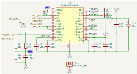
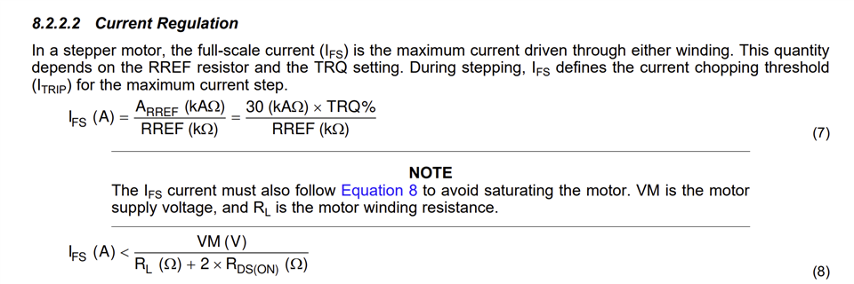
The matter of question is how to properly set up RREF voltage for a desired current limit of motor bridge regulation circuit of DRV8886AT. The chosen method is via PWM (from MCU not shown here). The left-most resistor divider ensures the voltage over the C19 capacitor is cca. 1.2V max during PWM ON cycles (3.3V from MCU). From my calculation the equivalent resistance of R9 and R10 is 16.6kOhm. This resistance with C19 gives the cutoff frequency of around 10Hz. The source (MCU) PWM frequency is 10kHz.

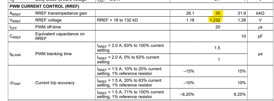
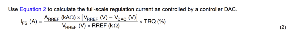
Now, the RREF resistor is set for 12kOhm which should result in a full-scale current of 2.5A. From my measurements on assembled PCB, 100% PWM DC gives the lowest current limit and 0% DC gives the highest current limit. However, it appears the full-scale current is still way below 2.5A because no matter the speed setting, the motor will not spin if M0 and M1 are set for full step setting. Also, the highest observed current per the whole motor was at the highest motor speed at 1/16 micro stepping setting and was 0.5A.

I guess I misunderstood how to set a full-scale current properly. However, I have followed the DRV8886AT datasheet and calculations to the point. So the question is how do I ensure my full-scale current is met? It seems the current limit is still too low for the motor to spin at full-step setting (the highest current consumption due to the highest torque).

  • Hi Luka,

    Thank you for posting in this forum.

    The RREF is reference resistor (not reference voltage input) pin which requires an external resistor to GND to set the IFS, full-scale current. The calculation for this resistor is based on ARREF(kAΩ), the transimpedance gain constant. The below snippet shows the section in the datasheet that describes IFS calculation. This pin is not meant for external VREF input in this device. 


    The following snippet shows the specification for ARREF. The range for RREF is 18 to 132 kΩ.

    Regards, Murugavel 

  • Hi Murugavel,

    Thanks for pointing out the range of Rref resistor. I have missed that info somehow when designing the driver circuit. The driver might not be responding the way I assumed since I used Rref = 12k which is below the valid range.

    You mentioned the pin the Rref connects to is not intended to be controlled by a voltage source. The DRV8886 datasheet mentions you can control the other end of Rref directly via DAC or PWM (via RC filter) as long as the voltage doesn't go over 1.2V. I can currently control the full-scale current like this but the max full-scale current is not reached. That's the only problem.

    Would the DRV8434 be a better fit for controlling Vref via DAC or PWM? I see that control from 0 to 3.3V is possible which is ideal for the MCU I'm using. Also, the DRV8434S, the SPI variant, if I understand correctly I just just set the the Vref to 3.3V (via pull-up?) and control the desired torque via SPI-accessible TRQ % setting.

    Best, Luka

  • Hi Luka,

    Based on the below equation, RREF defines the max current while external VDAC = 0 V. For the desired IFS RREF should be ARREF / IFS, so for 1.5 A IFS RREF would be 30/1.5 = 20 kΩ. The VDAC must be 0 V to achieve max current. I think R10 = 22 kΩ is acting in series to R14 and causing lower IFS. When VDAC = ~ 1.2 V the IFS would become 0. But with PWM DAC the series resistor R9 value impacts the current path. Adding an opamp buffer could address the impedance issue.

    That said, like you mentioned the DRV8434, DRV8434S are better fit for VREF control with external DAC. The VREF pin in these devices are high impedance. Current can be set with resistor dividers or a DAC. The one requirement to keep in mind is the source impedance must be < 50 kΩ.

    In the DRV8434S the current can be controlled by TRQ_DAC setting by keeping VREF fixed at 3.3 V. However, this approach provides only a 4-bit coarse control. If intermediate values of IFS would be required VREF must be changed. Usually the TRQ_DAC is kept at 100 % IFS and VREF is calculated based on the IFS requirement. The TRQ_DAC is scaled down to minimize hold current by setting it to a desired lower value when no STEP input pulses are input to reduce motor heat. Then just before applying step pulses TRQ_DAC can be set back to 100%. Thank you.

    Regards, Murugavel