This thread has been locked.

If you have a related question, please click the "Ask a related question" button in the top right corner. The newly created question will be automatically linked to this question.

DRV8832: drv8832, FAULT will operate

Part Number: DRV8832

Tool/software:

drv8832 schematic diagram.pdf

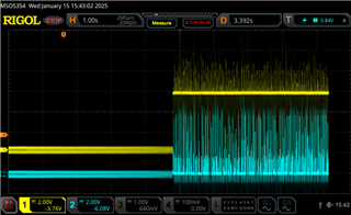
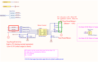
The input voltage of the motor does not go up, and the FAULT is pulled down at intervals

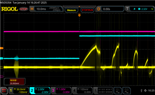
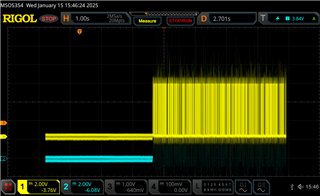
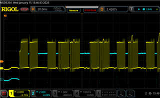
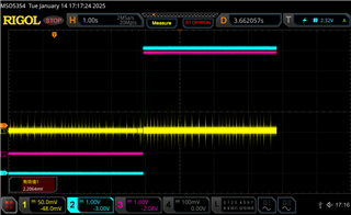
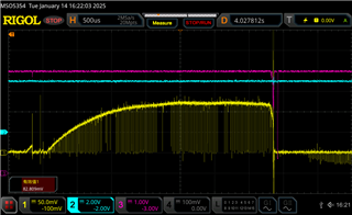
Digital ECB DRV8832, resulting in motor voltage not up to 5V, CH1,ISENSE; CH2,MOTOR+; CH3,FAULTn

Please help to find out what the problem is and how to solve it. Thank you!

MR+.MR-, provides high and low levels, M+M-, output waveform

Not sure if it is current protection or VSET voltage setting, there is a problem

ECB数位马达转速慢问题分析.docx

  • Hello,

    Please allow me some time to review this issue and I'll reply when I know more. 

    Best,

    David

  • I am in a hurry, please help to look at it as soon as possible, thank you!

  • any updated?thank you!

  • Hello,

    I'm looking into this now. I'll update shortly.

    Best,

    David

  • Hi Tony,

    Usually when we see nFAULT get pulled low it is due to overcurrent or thermal conditions. If possible, could you please provide more zoomed in screen shots triggering on falling edge of nFAULT with input, output voltages, and motor current.

    I'm also a bit confused as to the purpose of the resistor and capacitor connections on the output pins. Is it for filtering?

    Best,

    David

  • Removing the resistance and capacitor you mentioned has not improved, please help to see if there are problems in other places. In addition, the power supply looks very clean, but when the motor starts, the ground will have great interference, and the waveform is as follows

    Please help to check whether there is any problem with Layout

  • any update

  • Please help again to find out what the problem may be. If you can't find the specific problem, please inform us how to disable the function of PIN FAULTn without affecting the overall work of the chip, thank you!

    The current problems have affected the normal progress of the project.

    If there are any questions or additional information of you, can I add the relevant information for you

  • Hello,

    Can you provide the input sequence being used for MOTOR+ (IN1) and MOTOR- (IN2)? If driving a motor in the forward state it's recommended to hold IN1 high and PWM on IN2 (switching from forward to brake state). 

    If possible, please provide zoomed in scope captures to see inputs, outputs, and triggering on nFAULT going low. It would be good to see how long nFAULT is pulled low. 

    What's the load being used? If using a brushed-DC motor, how much continuous current is needed to drive and what's the stall current rating for the motor? Is the motor spinning while they tests are being conducted, and if so, does the problem persist when the motor/load is removed?

    Best,

    David