Other Parts Discussed in Thread: DRV8889-Q1
Tool/software:
Hi, team.
This is the stall detection data from TI.
Can you tell me what each waveform represents?
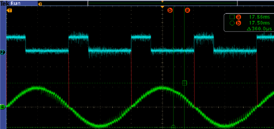
Blue: STEP?
Green: Motor current?
Yellow: Motor output voltage?
Best, regards.
Original question:

Tool/software:
Hi, team.
This is the stall detection data from TI.
Can you tell me what each waveform represents?
Blue: STEP?
Green: Motor current?
Yellow: Motor output voltage?
Best, regards.