This thread has been locked.

If you have a related question, please click the "Ask a related question" button in the top right corner. The newly created question will be automatically linked to this question.

Short circuit at output destroys DRV8231A motor controller

Part Number: DRV8231A

Tool/software:

Hello TI Team,

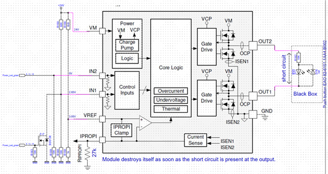
I have a problem with the DRV8231A module.
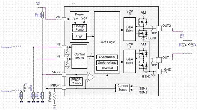
The circuit shows the current setup which switches the LEDs at the output. If the 24V are switched on, the red LED lights up. If the device is switched on from standby, the two power LED inputs can be switched by the µP. It is then possible to switch to green or switch off both LEDs.  The LEDs and the series resistor are only shown in principle as this is located entirely in the power button.
The current limitation for both switching states works.
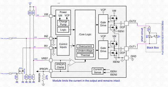
If I short-circuit Out1/2 when both power LED inputs are 0V then the module breaks.
If both inputs are at 3.3V then the green LED lights up and I can short-circuit the output and the current is limited without destruction.
I don't currently understand why this doesn't work in the default setting.

  • Hello,

    Thanks for your question.

    The expert from my team will review and get back to you.

    Thanks,

    Ibinu

  • Hello Ibinu,

    thank you for your message. Can you estimate when you will receive an answer from the expert?

    Best regards

    Philipp

  • Hello,

    I'm a bit confused by your question. Are you asking if it's possible to short the outputs (OUT1-->OUT2) and still limit the current? If the outputs are shorted, then a direct path from VM to GND (shoot-through) is made and this will damage the device. 

    Best,

    David

  • Hello David,

    the data sheet refers to the OCP.
    Here is the data sheet section in which the OCP is described for each of the four FETs in the bridge.


    As the LED is connected to the circuit board via a plug, there are various possibilities for a short circuit to occur. The circuit should therefore be protected.
    This works wonderfully for one direction. Unfortunately, it doesn't work in the other direction. But I can't see what's different as it only works in one of the two states.

    Best regards

    Philipp

  • Hello Philipp,

    If I understand your setup correctly, I believe this issue could be when IN1 = IN2 = 0, then the FETs are disabled, and the outputs are in a high-z state. During this time all the current would be to the "module" and not the device. 

    You are correct, each FET is protected by OCP but only when the FETs are on, and current is flowing through them. 

    Best,

    David

  • Hello David,

    Thank you very much for your reply. I have no problems in the state that IN1 = IN2 = 0. In the state IN2=1 IN1=0 I also have no problems here the current limitation takes effect as desired. My problems arise when IN1=1 and IN2=0. In my opinion, the overcurrent limitation does not work in this state.
    However, I assume that the external wiring is the problem. I have swapped the connections IN1 and IN2 as well as OUT1 and OUT2 on the IC directly as a test. The result here is no problem with IN2=1 IN1=0, but destruction with IN2=0 and IN1=1. I hope I have now described it understandably.

    Best regards

    Philipp

  • Hi Philipp,

    It seems the issue is when you are driving in the forward direction. When driving in the forward direction, the current is flowing from OUT1 to OUT2. The way the load is configured, it looks like there is no current limiting resistor to limit the current flowing into D78. Depending on the current rating of the diode, it's possible that it's too high and burning out.


    Is it possible to add a 10k resistor from OUT1 to load?

    The Overcurrent protection trip point (IOCP) for this device 3.7A. This means if the current through the load reaches 3.7A for longer than Overcurrent protection deglitch time (tOCP = 1.5us typically) then the outputs will disable to protect the motor driver. 

    Current regulation is used to set a maximum current threshold below this IOCP threshold. This ITRIP threshold will limit the current to this value and never reach IOCP. If wanting to use current regulation it can be set by the following formula:

    The ITRIP parameter depends upon the external VREF voltage and RIPROPI resistance as well as the internal AIPROPI current gain.

    Are you using current regulation in your design? What's the VREF and RIPROPI values?

    Best,

    David

  • Hello David,

    thank you for your detailed answer. Unfortunately, I can't follow you on the first point. The two LEDs in the push-button are connected antiparallel so that the red or green LED lights up depending on the direction of the current. The resistor is active in both current directions. Therefore, I cannot understand what another resistor in series to the circuit is supposed to do. But that is not my problem here either. If the output is not short-circuited, everything works as it should.

    I do this test because the LED is connected to the circuit board via a cable and a short circuit could occur here. I therefore tested the module for a short circuit and found that it does not work as expected.


    Therefore, I have taken two new pictures to try and describe the problems again.


    The first picture shows the operating case in which everything works as desired.

    All voltage values and all resistor values are in the circuit diagram. The green LED lights up until I short-circuit at the output. As soon as the output is short-circuited, the current is limited and checked every few ms to see if the short-circuit is still present. If the short circuit is removed, the LED lights up again. This means that the module has survived the short circuit and everything works as desired.


    I should also say that the two LEDs are installed in an EAO pushbutton - I have no idea what is actually in the switch. I have therefore added this as a schematic diagram. At 24V supply voltage, the red or the green LED need about 8mA.


    The problem now arises in the second screen. The input voltages have changed. This results in the voltages shown at the inputs. As long as there is no short circuit at the output, the red LED lights up as desired. If the output is short-circuited, the DRV8231A is destroyed. Neither the overcurrent protection, which is set to approx. 55mA according to the formula, nor the short-circuit current limitation work correctly in this case. After a short circuit at the output, the module itself is destroyed and now has a short circuit internally.


    At this point I am unfortunately stuck and would like to know what the problem is that the circuit can withstand the short circuit in one direction but not in the other.


    Best regards

    Philipp

  • Hi Philipp,

    Thank you for the explanation. I'll recreate this in the lab on Monday and let you know what I find.

    Best,

    David

  • Hi Philipp,

    In the lab, I was able to recreate the setup and successfully short the outputs in forward and reverse direction. The device returned to normal operation after each test. 

    The scope shot above shows the device in reverse mode with IN1 = 0 (yellow), IN2 = 1 (blue), OUT1 (purple), and output current (green) that's shorted from OUT1 to OUT2.

    The scope shot above shows the device in forward mode with IN1 = 1 (yellow), IN2 = 0 (blue), OUT1 (purple), and output current (green) that's shorted from OUT1 to OUT2.

    In a short circuit event, it is expected for the current to rise well above the OCP and current regulation threshold. There is an internal analog current limiting circuit that will limit the current in these events as to not damage the device. Please see the following app note for more on the analog current limiting circuit: Understanding Motor Driver Current Ratings (Rev. A) 

    For your test, are you using a bench power supply for your VM voltage? If so, what's the current limit? 

    Best,

    David

  • Hello David,

    thanks for the detailed measurements. I think I have found the problem. When switching from red to green, I switch several capacities for DC/DC converters on and off.
    In the case where the red LED is on, I only have 200nF capacitance on the VCC pin. When switching to green I have an additional 60µF on the 24V supply. As a test, I have now soldered 20µF to the VCC pin of the DRV8231A since then the current limiting works as desired.
    The laboratory power supply I use to operate the circuit is set to a maximum of 1A. However, it is currently not clear to me why the circuit needs the capacitance at the input if I set the current at the input to 1A and the fets in the motor driver can actually switch up to 3.7A.

    Best regards

    Philipp

  • Hi Philipp,

    Glad you've found the issue. The bulk caps act as reservoirs of electrical charge to keep the supply voltage stable during motor current variations. Short circuit events cause large energy demands from the supply which could have led to this issue. The bulk caps supply the initial current demand and provide some relief from the power supply. 

    Best,

    David