This thread has been locked.

If you have a related question, please click the "Ask a related question" button in the top right corner. The newly created question will be automatically linked to this question.

DRV8711: Heating Issue Before Programming

Part Number: DRV8711

Tool/software:

Hello TI Team,

I am using the DRV8711 stepper motor driver in my design, and I am experiencing excessive heating on the DRV8711 chip even before programming or connecting a motor. Below are the details of my setup and troubleshooting steps taken so far.

Small blue diamond System Details:
Motor: Not connected yet
MOSFETs Used: STD12NF06L-1 (Q_g = 14 nC)
Power Supply (VM): [Specify your voltage, e.g., 24V]
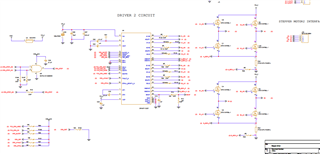
PCB Design: Custom board
Firmware: No SPI programming yet (fresh board)

Small blue diamond Observations:
1️⃣ DRV8711 heats up even before SPI configuration.
2️⃣ PCB power turns off when VM is connected (possible overcurrent issue).
3️⃣ A1_HS, A2_HS, B1_HS, B2_HS have internal pull-downs, but no external pull-downs are present.
4️⃣ Bootstrap capacitors (100nF) are correctly placed for high-side MOSFETs.
5️⃣ No visible short circuits on PCB.
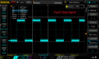
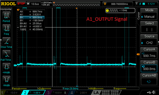
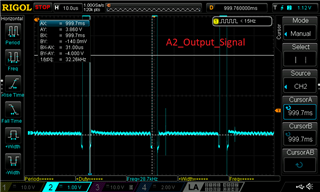
Small blue diamond Debugging Steps Taken:
White check mark Measured A1_HS, A2_HS voltages before programming – No unexpected high voltages observed.
White check mark Checked TOFF default setting – DRV8711 defaults to 0x30 (24 µs, ~42 kHz PWM), which should be fine for my MOSFETs.
White check mark Checked VM voltage stability – No significant dips. No short found


Small blue diamond Questions:
1️⃣ Why is the DRV8711 heating up before programming, even without a motor connected?
2️⃣ Could the internal pull-downs be insufficient, causing unintended MOSFET conduction?
3️⃣ Is there a recommended way to verify if the driver is unintentionally enabling FETs before SPI initialization?
4️⃣ Are there known issues where incorrect bootstrap capacitor behavior could cause heating?

Any insights or additional debugging suggestions would be greatly appreciated!

Thanks in advance for your support.

  • Hi Arun, 

    Thank you for posting in this forum. 

    General reasons for IC heating are:
    1) Switching currents to charge and discharge the FET gate capacitance both inside and outside of the device require current. This current travels through resistive paths creating power loss.
    2) Regulators dropping voltage across transistors to create stable output voltages to drive internal logic, external circuitry, and low side FETs.
    3) Other internal circuitry.

    I would like to ask some questions. 

    1) would you please check that the IC thermal GND is soldered properly? Although the IC itself does not have large power dissipation as compared to the power FETs, it can become hot if the thermal GND is not properly soldered down to the PCB of if there is not enough GND copper underneath the thermal PAD.

    2) Please configure the ProDrivers registers properly as mentioned in Section 7.3.8 P22 of datasheet. ( Link )

    3) Based on the IDRIVE and TDRIVE setting, select the appropriate external FET as mentioned in Section 7.3.9 P22 of datasheet ( Link )

    4) how much is the calculated Rsense?

    5) Please check the followings, to set you fpwm.

    Please let me know if you need any more help.

    Best regards, 

    Mojtaba.

  • Hi Mojtaba,

    Thank you for your response.

    I have attached the schematics in PDF format for your review. Since this is a fresh board and has not been programmed via SPI yet, I would like to understand the possible reasons for the heating issue.

    I will check your suggestions and proceed with programming the driver. Once programmed, I will update you with the results.

    Looking forward to your feedback on the schematics.

    Best regards,
    Arun

    et_stepper_driver_131224 - ba - copy.pdf

  • Hi Arun,

    VCP pin is connected to VM directly!

    VCP pin should be connected through C48 to VM.

    Regards,

    Grzegorz

  • Hi Grzegorz,

    Thanks for pointing out the mistake. We have cut the trace between VCP and VM and connected via a capacitor between them. While this has resolved the heating issue, we are still not getting any output on VINT (1.8V) and V5 (5V). The SLEEP pin is high, and RESET is in a low state.

    Would appreciate any suggestions you might have.

    Best regards,
    Arun

  • Hi Grzegorz,

    Thanks for pointing out the mistake. We have cut the trace between VCP and VM and connected via a capacitor between them. We have changed new driver IC. While this has resolved the heating issue, we are still not getting any output on VINT (1.8V) and V5 (5V). The SLEEP pin is high, and RESET is in a low state.

    Would appreciate any suggestions you might have.

    Best regards,
    Arun

  • Hi,

    We are now getting the expected voltages after re-soldering the pins. However, we are still unable to communicate over SPI. There is no activity on the MISO line, and it remains high. We have checked with all four modes.

    Any suggestions on what could be causing this?

    Best regards,
    Arun

  • Hi Arun,

    I am glad to hear one problem has been solved. As far as I remember my problem with SPI communication was that DRV8711 SCS pin had an inverted polarity to MCU SPI peripheral SCS pin and I used an inverter to solve it. DRV8711 SDATO pin also needs an external pull-up resistor. You can also compare with an oscilloscope signals on SPI lines to those on EVAL board or DRV8711 datasheet. Another way of finding the problem would be to use SPI signals from EVAL board.

    PS. Just took a look at your diagram. There is pull-up resistor R156 on MISO line - that is OK. I think you do not need pull-up resistor R114 on DRV8711 SCS pin.

    Regards,

    Grzegorz

  • DRV8711 OCP Issue – Gates Toggle Properly When MOSFETs Are Disconnected

    OCP Issue in our design and are experiencing an Overcurrent Protection (OCP) fault.  but the OCP bit is set in the STATUS register (0x07).

    Observations:

    • The gate signals toggle correctly when the MOSFETs are disconnected.
    • When the MOSFETs are connected, OCP is triggered immediately.
    • SLEEP is HIGH, and RESET is LOW during operation

    Could you provide insights into possible causes of OCP triggering only when motor are connected? Are there additional debugging steps or register configurations we should check?Any hardware changes?

    Your assistance would be greatly appreciated.

    Best regards,
    Arun

  • Hi Arun,

    Can you clarify when OCP fault occurs and when DRV8711 works OK?

    - DRV8711 works OK - MOSFETs are present on PCB board yes/no, motor is connected to PBC board yes/no,

    - OCP fault occurs -  MOSFETs are present on PCB board yes/no, motor is connected to PBC board yes/no.

    I would start with the following settings:

    ISGAIN - 10

    DTIME - 850ns

    TORQUE - 100

    TOFF - 30us

    TBLANK - 0x80

    DECMOD - Use auto mixed decay at all times

    OCPTH - 500mV

    OCPDEG - 2us

    TDRIVEN - 2us

    TDRIVEP - 2us

    IDRIVEN - 100mA

    IDRIVEP - 50mA

    Regards,

    Grzegorz

  • Hi,

    DRV8711 works OK - MOSFETs are present on PCB board yes/no:YES, motor is connected to PBC board yes/no, YES

    OCP fault occurs -  MOSFETs are present on PCB board yes/no, YES motor is connected to PBC board yes/no. YES

    But motor not spinning.

    Regards,

    Arun

  • Hi,

    During debugging motor drives like DRV8711 very helpful are oscilloscope current probes to monitor motor phase current.

    Cheap probes like the one below should be good enough most of the time.

    https://www.tme.eu/pl/en/details/cc-65/meters-and-ac-dc-clamp-probes/hantek/

    Regards,

    Grzegorz

  • Hi,

    Thank you for your response. After changing the MOSFET, OCP not occurring.

    We have configured the driver with the register initialization parameters as you mentioned. However, the output is still not being driven properly through the output channels (A1, A2, B1, and B2).

    We are providing a step pulse at 400 Hz with a 50% duty cycle, but the output is not changing as expected based on the input step pulse. Output is stable even if we change the pulse switching. Please find the attached image of the input and output signals for your reference. Kindly guide us to resolve this issue.

    Regards,

    Arun 


  • Hi Arun,

    I can not see anything wrong with output voltages, T_off is around 30us what is good and according to settings. I guess you use DRV8711 in indexer mode ie.

    PWMMODE is set to 0. In this mode DRV8711 sets automatically PWM duty cycle to get desired motor phase current and PWM duty cycle depends on VM voltage, motor parameters, motor speed and its BEMF voltage. If you set microstep MODE to 1/16 or more motor phase current should ideally get sinusoidal shape like on Figure 16 in DRV8711 datasheet. The easiest way to measure phase motor current is with current probe. Does your motor spin?

    Regards,

    Grzegorz 

  • Hi Arun,

    Please let us know if your issue is resolved. Like Grzegorz mentioned please try to use a current probe to get the current waveform for coil A or B. Be sure the DRV8711 is set to indexer mode - default setting of OFF register, PWMMODE = 0.

    Regards, Murugavel