This thread has been locked.

If you have a related question, please click the "Ask a related question" button in the top right corner. The newly created question will be automatically linked to this question.

DRV8434S: DRV8434S

Part Number: DRV8434S

Tool/software:

Hi,


I try to use DRV8434SRGER stepper motor driver in our design.

It connected to micro-controller with SPI interface.

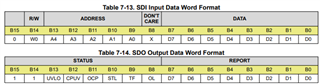
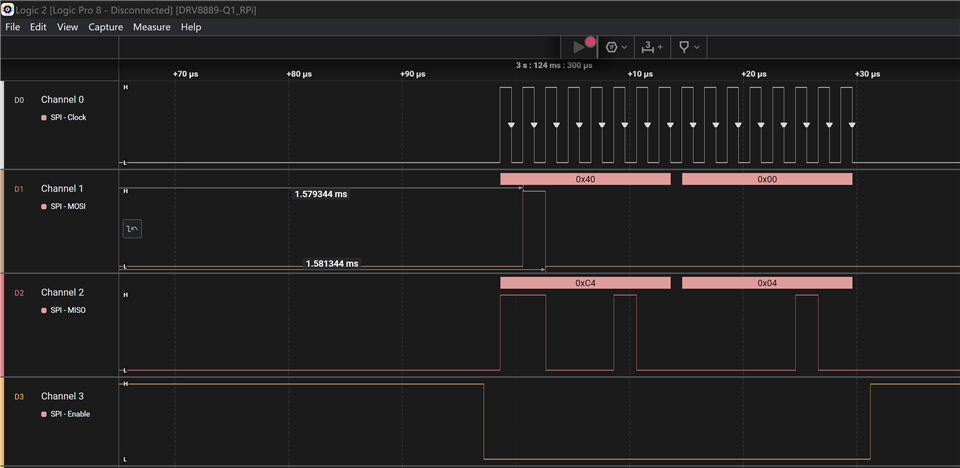
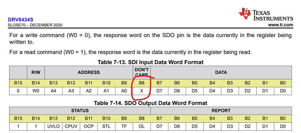
The sent 16-bit word 0x4800

I try to read CTRL2 register. It has the default state 0x0f.

According to the datasheet the CTRL2 default value is 15 (00001111).

But I see always zero on SDO line.


Please help.

  • Hi Igor, 

    Thank you for posting in this forum. The SPI frame and timing have significant effect on its operation. Please consider the following points.

    For detailed information please refer to 7.5.1 Serial Peripheral Interface (SPI) Communication of datasheet here

    1- SPI Format

    The SDI input data word is 16 bits long and consists of the following format

    • 1 read or write bit, W (bit 14)

    • 5 address bits, A (bits 13 through 9)

    • 8 data bits, D (bits 7 through 0)

    The SDO output-data word is 16 bits long and the first 8 bits make up the Status Register (S1). The Report word (R1) is the content of the register being accessed.

    2- Timing requirements. 

    The SCLK pin must be low when the nSCS pin goes low and when the nSCS pin goes high.

    • The nSCS pin should be taken high for at least 500 ns between frames.

    • Full 16 SCLK cycles must occur.

    • Data is captured on the falling edge of the clock and data is driven on the rising edge of the clock.

    • If the data word sent to SDI pin is less than 16 bits or more than 16 bits, a frame error occurs and the data word is ignored.

    • For a write command, the existing data in the register being written to is shifted out on the SDO pin following the 8-bit command data.

    Please consider the following timing. 

    If the issue still exists, please share the waveform including nSCS, SCLK, nFAult, and SDI.  

    Please reach out if you have any more questions. 

    Best regards

    Mojtaba. 

  • Hi Mojtaba,

    Thanks for your answer,

    But it didn't help me at all.

    I read the protocol description in the DRV8434S datasheet.

    All signals that the micro-controller sends exactly match all these requirements.

    I send 0x4800 word to read register CTRL2.

    The timing diagram is match to requirements.

    Connection of DRV8434S pins:

    SDI connected to SPI MOSI

    SCLK connected to  SPI SCK

    nSCS connected to  SPI NSS

    SDO connected to  oscilloscope to see the output signal

    VSDO, ENABLE, nSLEEP, DVDD connected to 3.3V

    All GND pins connected to GND.

    Why is there no signal on the SDO line?

    Best regards,

    Igor.

  • Hi Igor,

    Sorry to hear you were still facing issues. Like Mojtaba mentioned likely an SPI communication issue assuming there are no hardware issues. I assume you were testing with your own PCBA for the DRV8434S. 

    The timing diagram is match to requirements.

    Connection of DRV8434S pins:

    SDI connected to SPI MOSI

    SCLK connected to  SPI SCK

    nSCS connected to  SPI NSS

    SDO connected to  oscilloscope to see the output signal

    VSDO, ENABLE, nSLEEP, DVDD connected to 3.3V

    All GND pins connected to GND.

    Why is there no signal on the SDO line?

    This description looks correct. See below example of one frame SPI transaction capture of a read-only register.

    One important thing to verify is how you set the upper 8-bits for the address - see below. The address bits are left-shifted by one position in this device. 

    Could you please capture all four SPI signals like the example shown. Thank you. 

    Regards, Murugavel