Tool/software:
DRV8323HRTA EMI Performance is poor,this is our schematic.
How to improve EMI performance through circuit change?
Thanks!
This thread has been locked.
If you have a related question, please click the "Ask a related question" button in the top right corner. The newly created question will be automatically linked to this question.
Tool/software:
DRV8323HRTA EMI Performance is poor,this is our schematic.
How to improve EMI performance through circuit change?
Thanks!
Hello,
What is the frequency of the EMI that is being observed?
Check out this app note to optimize your layout: https://www.ti.com/lit/an/slva959b/slva959b.pdf?ts=1710808643945&ref_url=https%253A%252F%252Fwww.google.com%252F
Regards,
Yara
our layout follow TI app note.
Should we add gate resistor,or adjust IDRIVE pin?
Regards,
yx,yan
Hi yan,
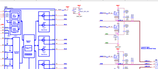
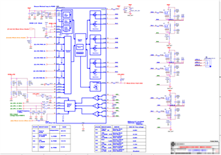
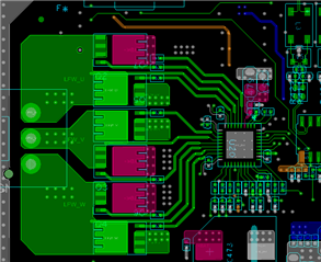
The schematic looks good, I don't see anything that is concerning. Can you tell me a little more about the EMI that is being observed?
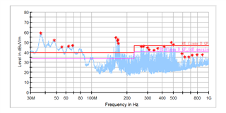
Can you test to see at what point the EMI is present? When the devices in on? When the device is on and switching the gates? When the device is in sleep mode?
Regards,
Yara
Can we add a resistor series with the capacitor between CPH and CPL?
When motor work,EMI Fail.
No a resistor can not be added in series with the capacitor CPH-CPL.
So EMI is only present when the motor is spinning?
Regards,
Yara
No a resistor can not be added in series with the capacitor CPH-CPL.---Can you explain why?
So EMI is only present when the motor is spinning?---Yes,only motor is spinning.
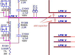
The behavior of the charge pump will be affected if a resistor is added in series with the capacitors. There is internal circuitry that is dependent on the specific behavior of the charge pump so anything other than the recommended external components should not be used from CPH-CPL
What IDRIVE setting is being used? Have they tried the lowest IDRIVE setting and saw a change in EMI?
Regards,
Yara
Yes,we tried IDRIVE setting.It is helpful to improve EMI performance.But not enough.
Can we add capacitor to BLDC three phase line,for example,between UVW.
Thanks.
Regards,
Yan
Can you show where on the schematic you would want to add a capacitor?
Do you have waveforms for GHx to SHx, SHx to GND, and GLx to GND? Can you provide these waveforms using different IDRIVE settings?
Do you have a layout that can be reviewed? often times EMI issues can stem from layout.
Regards,
Yara
Hi Yan,
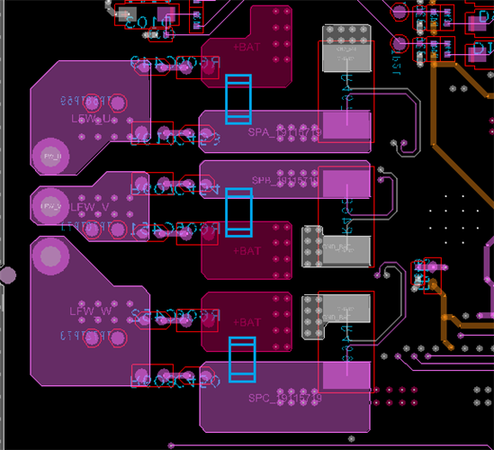
The capacitor placement is interesting, I haven't seen it implemented before but I did fins this research paper that discusses results using this method:
https://ieeexplore.ieee.org/document/6799414
but I again I really don't know if there something in this device that would prevent this from working.
We also have a video that discusses a few methods for reducing EMI:
https://www.ti.com/video/6297547663001
Regards,
Yara
I can not download IEEE file,could you please provide it,thanks.
Regards,
Yan
Hi Yan,
Here is that paper I linked.
Reduction_EMI_due_to_di_dt_and_dv_dt_DC_and_AC_sides_of_BLDC_motor_drive.pdf
Thanks Grzegorz for your input!
Regards,
Yara