


Other Parts Discussed in Thread: DRV8932, DRV3946-Q1
Tool/software:
Hi forum.
I need your help since I need to drive a low frequency (1Hz up to 150Hz) 24V - 500mA solenoid valve with the DRV8932 but I am having problem driving it with cycle-by-cycle method.
An MCU is providing a 2Hz digital signal with 40% duty cycle (200ms HIGH / 300ms LOW) applied to IN1.
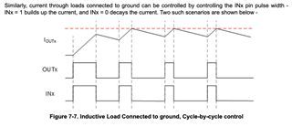
Wanted to try the method described by datasheet page 16. Where: "Similarly, current through loads connected to ground can be controlled by controlling the INx pin pulse width -
INx = 1 builds up the current, and INx = 0 decays the current."
But following problem occurs:
the valve gets engaged during first cycle and then does not switch off.
Valve has an output LED on the top that shows exact timing in sync with the MCU output but the valve dues not follow the MCU.
the connector has a freewheeling diode inside.
Playing with VREF I have seen that tied to VDD the valve gets first cycle ON/OFF (out of sync) and then remains engaged.
Please help

