This thread has been locked.

If you have a related question, please click the "Ask a related question" button in the top right corner. The newly created question will be automatically linked to this question.

MCF8316C-Q1: I2C No ACK

Part Number: MCF8316C-Q1
Other Parts Discussed in Thread: MCF8316AEVM,

Tool/software:

I designed a PCB implementing the MCF8316C-Q1, inspired from the development board MCF8316AEVM, but I am not able to get the I2C communication working. 

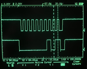
I implemented the I2C write and I2C read functions as per the datasheet (7.6.2.3-4), but see that the MCF8316C does not ACK following the target ID and 0 bit, as shown on the scope screenshots attached. The Target ID is 0x1, the left cursor is on the 0 bit (write) and the right cursor is where the MCF8316C should pull down to ACK. 

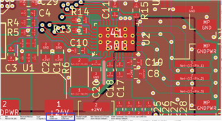
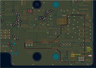
I also attached my schematic around the MCF8316C. All nets connect to the MCU. In-circuit measurements are noted in blue. Just note that I supplied the circuit with +12V rather than +24V, but that should not change anything. The logic level HIGH is 3.3V. All registers should be at default value, as I did not access

I suspected it had something to do with the sleep mode, but it still does not work when the SPEED/WAKE pin is kept high, which should be the wake condition required when the sleep mode is Analog Voltage (which should be by default?). 

Please help me troubleshoot this.

Thank you !

BLDC Controller.pdf

  • Hi Jean,

    Schematic is fine, only question I had is about pull up on SCL, SDA which I dont see in the schematics, is this available on your host controller side?

    I hope pull ups for all other pins are on your hist side which is not shown in this schematic.

    Can you use EVM, blue wire to your hardware and test?

    Thanks and

  • Hello, 

    Yes SCL and SDA both have strong pull-up resistors of 1k, so the edges are sharp. nFault and FG outputs are pulled-up by the MCU inputs.

    I made in-circuit measurements on the EVM board, and found some discrepancies with my circuit. I believe the buck regulator is malfunctioning, and that may cause the I2C issue. 

    I realize that the voltage on FB_BK (pin 3) should be pretty clean, and averaging 3.3V, 4V, 5V or 5.7V. Instead, I measure 1.9V average with a 1kHz, 0.3V p-p ripple. The same ripple is visible on DVDD (pin 1), I should read a clean 1.5Vdc, but I read a 1.2V with 1kHz, 0.5V p-p ripple. However, it is not visible on AVDD (pin 27), where I have a clean 3.3V. 

    I am now concerned with my layout, even though I did follow the guidelines and have experience with buck regulator designs. So here is a screenshot of L1 (mixed signals, ground and power) and L2 (power ground and signal ground). 

    Do you think the layout could be the cause ? What would you suggest to try next ? Would replacing the resistor with an inductor make sense ? 

    More importantly, would a buck regulator malfunction cause an issue with the I2C bus ?

    Thanks !

  • Hi Jean,

    Thanks for verifying the Buck stability issue. What is the component rating of Buck resistor used?

    There is a configuration BUCK_CL value, required configuration is 150mA, default setting is 600mA.

    Buck resistor rating should be > 0.5W.

    Can you highlight the Net tie connecting power ground and AGND in your layout?

    If you suspect, try blue wiring and verify again?

    Thanks and Best Regards

    Venkatadri S

  • R6 is a 2010, 0.75mW 22R. 

    To read/write BUCK_CL, I need the I2C interface to work though. 

    Here is the layout with the net tie highlighted. L2 is shown on top, it has an inner polygon for the power ground plane, and the rest is signal ground plane. They are both attached to the ground pin of the power supply connector J4. Therefore, I put the net tie close to that ground pin to split both planes as close as possible from the source. 

    Would it help to replace R22 with an inductor ? 

    What do you mean by blue wiring ? 

    Thanks, 

  • Hi Jean,

    Resistor rating is good. Blue wiring means try to wire ground path if we have to suspect that.

    Can you also check if Speed pin is stable high? If device is sleep mode then device can drop to sleep state.

    Let me recheck again schematics and layout.

    Thanks and Best Regards

    Venkatadri S

  • Oh, I found the issue ! 

    My CM did not install the specified resistor value for R_bk. 0.22R was installed instead of 22R. 

    The buck was limiting the current, preventing to reach a stable voltage, leading to the I2C issue. 

    Thank you for your help !