This thread has been locked.

If you have a related question, please click the "Ask a related question" button in the top right corner. The newly created question will be automatically linked to this question.

DRV8262: Single H-Bridge Bi-Directional Freewheeling when not running.

Part Number: DRV8262

Tool/software:

Good day! I am using the DRV8262 on a project, and I need to be able to freewheel both directions when the motor is not running. I have done this in the programming by simply putting the device to sleep (Both Outputs go to High Impedance) when the throttle is in a lower position.

The problem is that any time I engage the throttle while I am pushing the unit with the motor on the wheels, the controller abruptly "grabs" the motor, causing it to come to a complete stop before speeding up to the throttle speed. Is there any way to eliminate or at least dull the latch to zero speed when the motor comes to a halt? 

  • Hi Luke,

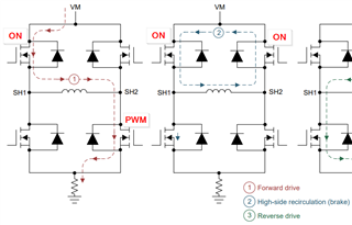
    The DRV8262 has two control modes, PH/EN and PWM. Depending on which control mode is being used, the outputs will have different output states that they can achieve. The PWM interface is popular because it allows the outputs to enter a Hi-Z state without having to put the device into a sleep mode. This allows the current to be recirculated in a Coast mode also known as fast decay. If you haven't already, I would try to switch to the Coast mode to recirculate current during the PWM off time or motor stop. 

    Best,

    David

  • Hello and sorry for the delay, I had to wait for sample parts to arrive to do my testing...

    So in order to turn the motor forward and make it coast during the off-time, I need to set IN2 to 0 then PWM IN1 correct?

    This is what I did first, and the Outputs follow each other, as in when I increase the duty cycle, the H bridge duty cycle increases forward and reverse, which makes a huge current and no motor rotation. 

    So I set IN2 to 1, but now PWM on IN1 backwards-modifies the motor speed....

    Please explain to me the signals needed at IN1 and IN2 to rotate the motor in a single direction with PWM, in which the motor coats in the off-time of the PWM and anytime the PWM is 0%...

  • Hi Luke, 

    It's suggested to switch between Forward and Brake (slow decay) states. The naming of the Brake state is misleading but means during the PWM off time the recirculation current will be sent through the two high-side FETs. To achieve this, set IN1 = 1 and PWM on IN2. 

    More on current recirculation and decay modes can be found in the following app note: Current Recirculation and Decay Modes (Rev. A) 

    Best,

    David

  • To achieve this, set IN1 = 1 and PWM on IN2. 

    I adjusted my circuit this way, and I still have the same problem...

    I think that the DRV8262 will not work for my application, I need something that will disconnect from both rails.
    What is wrong with the simple circuit below, I can drive both MOSFETs on to power the motor and both off to freewheel...

    Maybe I need a flyback diode from IN- to IN+?

  • Hi Luke,

    I'm a bit confused by the schematic provided. The DRV8262 is an integrated motor driver, which means the FETs are integrated within the device. Each of these FETs have a freewheeling diode to recirculate the current during PWM off time. 

    Best,

    David

  • My question is if the schematic I provided can work for what I need instead of the DRV8262.

  • Luke,

    I'm not sure I understand your circuit above. It looks like you are IN+ an IN- as the supply voltages for the motor. Typically, our inputs are used to control the gates of the FETs and a separate VM supply is used to power the motor. 

    If you haven't already, please use the DRV8262EVM for any design evaluations. 

    DRV8262EVM Evaluation board | TI.com

    Best,

    David

  • I am asking if a circuit without the DRV8262 and using those 2 MOSFETs instead would work for my circuit...

    I will have to use something else I guess, it seems the DRV8262 is too integrated for my needs...