Other Parts Discussed in Thread: CSD19532Q5B
Tool/software:
Hi TI,
I use DRV8353RH-EVM to drive motor and I only modify MODE on EVM (connect MODE to GND and set 6x PWM mode).
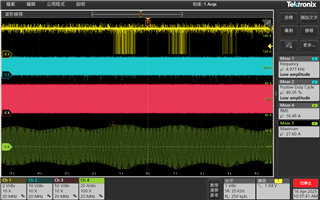
When I drive motor with heavy loading, I find a 20us pull low signal on nFAULT pin every 3~10 second.
I won't find this condition on light loading.
I can't find any protection which will pull low for 20us in datasheet.
Please refer to the waveform below.
C1: DC Bus, C2: nFAULT, C4: motor phase current
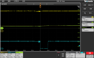

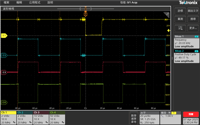 pic.1
pic.1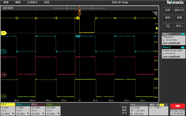 pic.2
pic.2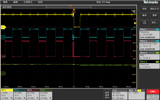
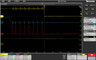 (ZOOM IN)