Other Parts Discussed in Thread: CSD88599Q5DC,
Tool/software:
Hello TI team,
I have designed a custom PCB using the DRV8323SRTAR and CSD88599Q5DC FETs for driving a 3 phase PMSM.
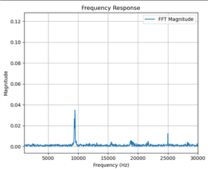
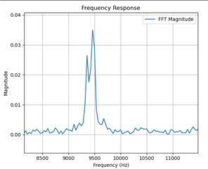
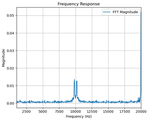
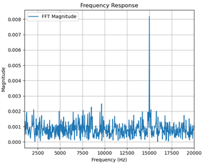
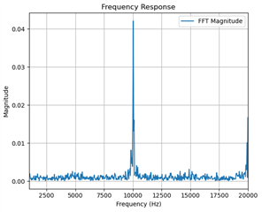
We are experiencing issues with audible noise at ~8.5kHz even when commanding zero torque. I will try to explain the situation and tests i have performed as detailed as possible.
The used motor is a R080 KV105 Lite.
Supply voltage is 48V but issues is also present at lower voltages.
I know 48V is above TI recommendations, we have designed a voltage clamper circuit to prevent overvoltage due to motor braking.
I have approx 500uF of bulk capacitance on the supply close to the FETs.
Each phase has a RC snubber circuit.
To isolate the issue i have completely removed any PI controllers.
I command a 50% dutycycle on all 3 phases, meaning the top 3 FETs are on simultaneously 50% of the time, same goes for the bottom 3 FETs.
Per my understanding this should result in no current running through the motor and i would expect the motor to be silent.
Using FOC, SVPWM with alternate reverse sequencing and Iq,Id PI controllers the motor is also noisy.
What i have tried, (all tests performed without PI controllers, just 50% duty)
I have tried disconnecting the motor which removes the noise.
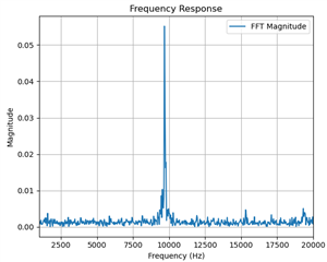
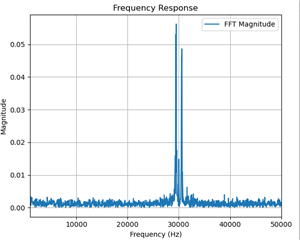
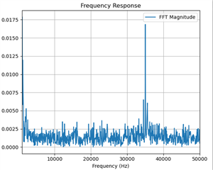
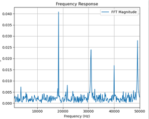
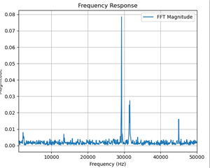
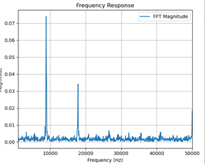
I have tried decreasing and increasing the PWM frequency in the range 10 kHz to 50 kHz. For some frequencies the audible noise is dominant at 8.1 kHz and for other PWM frequencies it is dominant at 8.7 kHz. Target PWM frequency is 25kHz
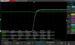
I have tried adjusting gate drive strength and measuring VGS, signals look clean without any ripple. Currently gatedrive strength is configured for at rise/fall time of ~200ns.
I have tried measuring the CPH and VCP on oscilloscope. VCP rises to VM+12 and falls to VM+10.5.
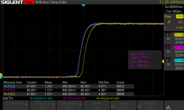
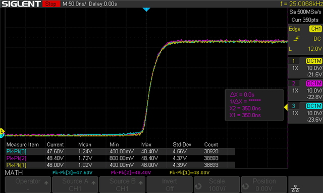
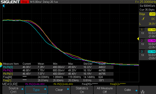
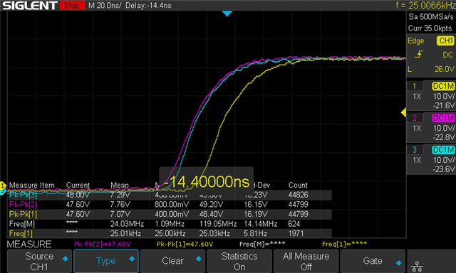
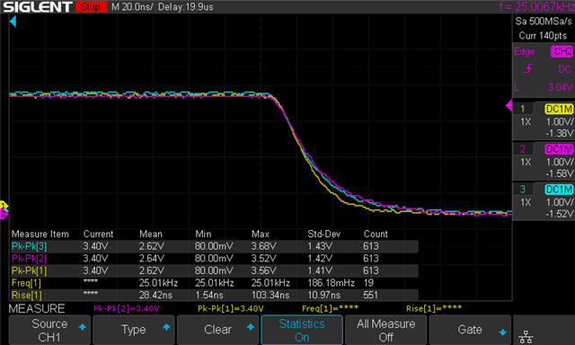
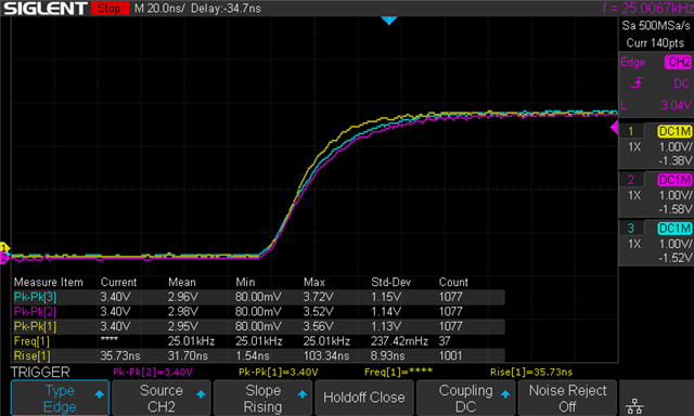
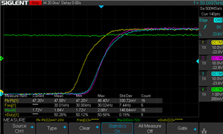
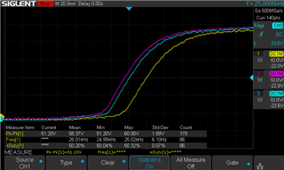
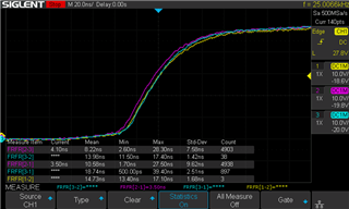
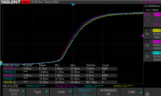
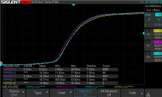
I have tried measuring the phase voltages with an oscilloscope. Here I primarily saw all 3 phase voltages rise/fall simultaneously. BUT i sometimes randomly saw one of the phase voltages was delayed by +- 20ns and i am concerned if this could be the reason for the audible noise.
I have tested 2 different PCBs and 2 different layouts, the issue persists.
I have tested 2 different motors the issues persists.
I have measured the supply voltage which has no significant ripple.
I have tried adjusting dead time with no changes.
I am consistently monitoring nFault of the gatedriver, it never goes low.
Any support on how to combat this issue would be greatly appreciated.
I am able to provide pictures of oscilloscope measurements if needed.
Schematic and layout can also be shared directly with TI employees.
Looking forward to hearing from you
Best regards,
Mads