Tool/software:
Hello,
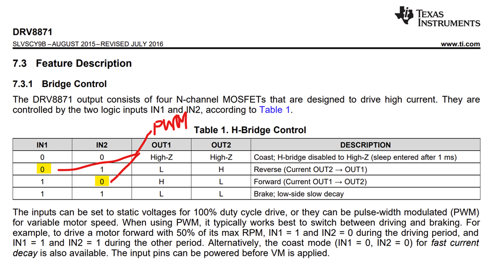
I am running into an issue when I try to run a motor without having it pulse, but as I increase the voltage it starts pulsing around 12-13V. I am using the Adafruit DRV8871 Brushed DC Motor Driver Breakout I have a 24V power supply connected to the power terminal of the DRV8871 and a microcontroller connected to IN1 and IN2. I also added a resistor to ILIM to change the max current rating from 2A to 3.6A. I'm not too familiar with how the motor driver board works but I have it running in forward direction (IN1 set to LOW and IN2 set to analogWrite as it gradually increases). I want to run the motor to run at 24V continuously without having it pulsate, how am I able to do so? I have a 30W motor which is well under the current the motor driver board can handle. I have attached the code I used that was provided from the Adafruit DRV8871 datasheet.
Datasheet: cdn-learn.adafruit.com/.../adafruit-drv8871-brushed-dc-motor-driver-breakout.pdf
Code:
// Basic sketch for trying out the Adafruit DRV8871 Breakout
#define MOTOR_IN1 9
#define MOTOR_IN2 10
void setup() {
Serial.begin(9600);
Serial.println("DRV8871 test");
pinMode(MOTOR_IN1, OUTPUT);
pinMode(MOTOR_IN2, OUTPUT);
}
©Adafruit Industries Page 12 of 16
void loop() {
// ramp up forward
digitalWrite(MOTOR_IN1, LOW);
for (int i=0; i<255; i++) {
analogWrite(MOTOR_IN2, i);
delay(10);
}
// forward full speed for one second
delay(1000);
// ramp down forward
for (int i=255; i>=0; i--) {
analogWrite(MOTOR_IN2, i);
delay(10);
}
// ramp up backward
digitalWrite(MOTOR_IN2, LOW);
for (int i=0; i<255; i++) {
analogWrite(MOTOR_IN1, i);
delay(10);
}
// backward full speed for one second
delay(1000);
// ramp down backward
for (int i=255; i>=0; i--) {
analogWrite(MOTOR_IN1, i);
delay(10);
}
}
I would appreciate any assistance in this.
Thank you!


