This thread has been locked.

If you have a related question, please click the "Ask a related question" button in the top right corner. The newly created question will be automatically linked to this question.

DRV8462: Reg: Fault register status

Part Number: DRV8462


Tool/software:

Hi Team, 

We are trying to drive the stepper motor PR57HS112-4204-01-R with DRV8462 driver, that initialized with following parameters,


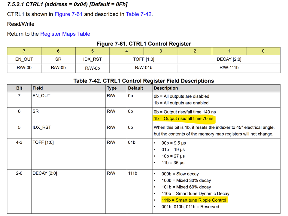
CTRL1_Register drv8462_ctrl1_reg = {
.EN_OUT = 1,
.SR = 0,
.IDX_RST = 0,
.TOFF = 1,
.DECAY = 0x7
};

CTRL2_Register drv8462_ctrl2_reg = {
.SPI_DIR = 0,
.SPI_STEP = 0,
.MICROSTEP_MODE = 0x3
};

CTRL3_Register drv8462_ctrl3_reg = {
.CLR_FLT = 0,
.LOCK = 0x3,
.TOCP = 1,
.OCP_MODE = 0,
.OTSD_MODE = 0,
.TW_REP = 0
};

CTRL4_Register drv8462_ctrl4_reg = {
.STEP_FREQ_TOL = 1,
.FRQ_CHG = 0,
.STL_REP = 1,
.EN_STL = 0,
.STL_LRN = 0,
.TBLANK_TIME = 1
};


CTRL5_Register drv8462_ctrl5_reg = {
.STALL_TH = 0x3
};


CTRL6_Register drv8462_ctrl6_reg = {
.STALL_TH = 0,
.TRQ_SCALE = 0,
.DIS_SSC = 1,
.RC_RIPPLE = 0
};

CTRL7_Register drv8462_ctrl7_reg = {
.TRQ_COUNT = 0xFF
};

CTRL8_Register drv8462_ctrl8_reg = {
.TRQ_COUNT = 0xF
};

CTRL9_Register drv8462_ctrl9_reg = {
.EN_AUTO = 0,
.RES_AUTO = 0,
.STEP_EDGE = 0,
.OL_T = 1,
.OL_MODE = 0,
.EN_OL = 0
};

CTRL10_Register drv8462_ctrl10_reg = {
.ISTSL = 0x80
};

CTRL11_Register drv8462_ctrl11_reg = {
.TRQ_DAC = 0xFF
};

CTRL12_Register drv8462_ctrl12_reg = {
.TSTSL_FALL = 0x4,
.EN_STSL = 0
};

CTRL13_Register drv8462_ctrl13_reg = {
.VREF_INT_EN = 0,
.TSTSL_DLY = 0x4
};

With the help of reference manual, we have set the hold current as 1.2A,

before connecting the load, we are getting the hold signal as output without any fault,

After connecting the stepper motor with driver, the Overtemperature shutdown occurred as per the fault register TF flag.

but we are not sensing any heat on thermal pad.

Kindly help us to resolve this issue.

Thanks and regards,

Sugadev S 

  • Hi Sugadev,

    The current per phase specification of this motor seems to be 4.2 A. What was the VREF voltage used and the VM supply voltage used? 

    After connecting the stepper motor with driver, the Overtemperature shutdown occurred as per the fault register TF flag.

    but we are not sensing any heat on thermal pad.

    As soon as the shutdown happens the IC can cool fast enough you won't be able to sense any heat on the thermal pad. But you may be able to see it with a thermal camera with high frame rate. Was this tested with TI DRV8462EVM or your PCB. If it is your PCB it is likely there may be thermal related issues. Was the thermal pad and thermal vias made in compliance with TI recommendations for this device?

    The EVM HW Altium files can be downloaded from the EVM webpage, https://www.ti.com/tool/DRV8462EVM. The EVM HW was tested with 24 V VM and 5 A per phase current setting with no thermal issues. But this won't work for 48 V VM and 5 A per phase current setting. In this case you should consider DRV8462 in DDV package which features external heatsink. 


    Thank you.

    Regards, Murugavel 

  • Hi Murugavel,

    Thank you for your prompt response.

    We are providing VREF = 0.792 V, VM supply voltage = 24 V, and setting CONTROL10_REG.ISTSL to 0x80 for 50% output current. We are using the DDV package.

    Is it necessary to add a heatsink with a thermal pad for operation under these conditions?

  • Meanwhile, I'm adding the screenshot of our hardware schematic. Let us know if it is necessary to add the PCB layout for your review. 

  • Hi Sugadev,

    We are providing VREF = 0.792 V, VM supply voltage = 24 V, and setting CONTROL10_REG.ISTSL to 0x80 for 50% output current. We are using the DDV package.

    Is it necessary to add a heatsink with a thermal pad for operation under these conditions?

    Most definitely, yes. The DDV package thermal pad is on the top side and the chip heat can be dissipated via the pad only. So if no heatsink is provided the pad will heat up fast and a TSD will happen.

    Regards, Murugavel 

  • Hi Sugadev,

    Meanwhile, I'm adding the screenshot of our hardware schematic. Let us know if it is necessary to add the PCB layout for your review. 

    The schematic looks okay. DDV must be used with an heatsink even if low current setting. 

    Regards, Murugavel 

  • Hi Murugavel,

    Thank you for your suggestion.  We will add a heat sink and check. 

    Regards,

    Sugadev S

  • Hi Murugavel,

    We are adding a heatsink with the driver and trying to run the stepper motor, but the problem has not been resolved. The same "Overtemperature Shutdown" occurred as indicated by the TF flag in the fault register. 

    Could there be any other causes for this issue ?

  • Hi Sugadev,

    We are providing VREF = 0.792 V, VM supply voltage = 24 V, and setting CONTROL10_REG.ISTSL to 0x80 for 50% output current. We are using the DDV package.

    Was the above conditions the test case when the problem happens? How long does the stepper motor run before having a OTSD? Could you please share the image of the heatsink mounted on the device as well as the temperature of the heatsink? Thanks.

    Regards, Murugavel 

  • Hi Murugavel,

    Please find the attached images of the heat sink mount. It seems the hold output was active for only 1 to 2 seconds, after which OTSD (over-temperature shutdown) occurred. When we cleared the fault status, the driver recovered to normal but then entered the OTSD condition again. Currently, we do not have a temperature measurement setup available.

    Regards,

    Sugadev 

  • Hi Sugadev,

    Thanks for the images. It appears the heatsink was positioned and glued to the top of the IC and not secured with screws to the PCB. This cannot guarantee proper interfacing with the thermal pad, especially if the heatsink is just a flat surface it will have a thermal interface failure in most cases.

    The attached heatsink is used in our EVM and was tested to operate with 24 V and 10 A setting. 

     2018.ATS-TI10P-519-C1-R3.pdf

    You can see it has a projected surface to properly interface with the top thermal pad of the driver IC. See below.

    Based on your image the driver is toward the edge of the heatsink. This is not best practice mechanically. The center of the heatsink must be positioned on the top of the IC as well as, at the interface between the heatsink and the IC the heatsink must not have any paint - must have clean bare metal and pressed firmly against the IC thermal pad with thermally conducting paste used for full surface contact. Otherwise the heat generated cannot be dissipated by the heatsink and will result in TSD.

    Regards, Murugavel 

  • Hi Murugavel,

    We have replaced the heat sink with one similar to what you mentioned. The driver is now positioned toward the center of the sink, and it is an adhesive-type heat sink. In the hold condition, we can feel that the motor is holding, and there is no fault. However, when we start driving the step pulse, the OTS fault occurs immediately. what could be the reason?

    Regards,

    Sugadev

  • Hi Sugadev,

    An OTS fault indicates the die temperature was exceeding the TOTSD temperature. This happens when the driver IC dissipates a lot of power and the heat is not effectively removed from the IC. For proper thermal conduction metal-to-metal interface between the IC metal thermal pad and the heatsink with thermal conducting paste is suggested. Adhesive-type heatsink do not match metal-to-metal heatsink performance. 

    We are providing VREF = 0.792 V, VM supply voltage = 24 V, and setting CONTROL10_REG.ISTSL to 0x80 for 50% output current. We are using the DDV package.

    Were the test conditions same as above? Assuming so, the run current would be 2.4 A and hold current would be 1.2 A (ISTSL = 50 %). So hold did not dissipate that much power compared to the run mode. The driver IC was tested in the DRV8462VEVM with a 10 A stepper motor and 24 V supply with no issues - heatsink as shown in image below mounted metal-to-metal with thermal conducting paste and bolted to the PCB for optimum thermal conduction.

    Using faster SR and STRC decay mode can help minimize the power dissipation during motor run. Thank you.

    Regards, Murugavel 

  • Hi Murugavel,

    We are encountering the same error even under a no-load condition (with no motor connected). We have also tested it using the 50% run current setting.

    Regards,
    Sugadev

  • Hi Murugavel,

    Can you suggest any configuration settings for this application?

    VM = 24 V
    Motor Phase Current = 4.2A

    Regards,
    Sugadev

  • Hi Sugadev,

    Can you suggest any configuration settings for this application?

    VM = 24 V
    Motor Phase Current = 4.2A

    With default register settings to begin with, if you configure EN_OUT = 1 in the CTRL1 register and provide VREF = 1.32 V and provide STEP input the stepper should run with ~ 4.2 A. You can try with a lower current for example 1 A or VREF = 0.33 V to see there are no electrical issues in your PCB. Unloaded motor should still run with 1 A. 

    We are encountering the same error even under a no-load condition (with no motor connected). We have also tested it using the 50% run current setting.

    After getting a fault error, nFAULT = 0, can you read the FAULT, DIAG1, ,2, 3 registers and share for review? Thanks.

    Regards, Murugavel 

  • Hi Murugavel,

    We configure with default values in CTRL 1 register and provide VREF = 0.758 V, Current setting = 1.07 A

    After getting a fault error registers value are,

    FAULT Register = 1000 1000

    DIAG1 Register = 0000 0000

    DIAG2 Register = 0000 0000

    DIAG2 Register = 0100 0010

    When we are observing these register values OCP fault bit is set in fault register, but no corresponding fault appears in the DIAG1 register.

    Regards,
    Sugadev

  • Hi Sugadev,

    Thanks for checking and sharing the information.

    We configure with default values in CTRL 1 register and provide VREF = 0.758 V, Current setting = 1.07 A

    If you set VREF = 0.758 V then the current IFS would be 2.3 A. Did you modify the TRQ_DAC CTRL11 register to get 1.07 A?

    When there is an OCP the DIAG1 must show specific fault whether HS or LS FET and which FET(s). Not sure if the device was damaged already. Did you try with multiple devices to verify the faults? Thank you.

    Regards, Murugavel