This thread has been locked.

If you have a related question, please click the "Ask a related question" button in the top right corner. The newly created question will be automatically linked to this question.

DRV8262EVM: No Output with STM Microcontroller on DRV8262EVM

Part Number: DRV8262EVM

Tool/software:

Hello everyone,

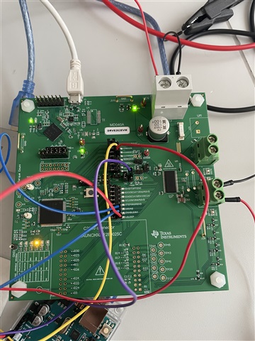
I would like to control my DVR8262EVM with an STM microcontroller, but there is no Output.
The output of the STM is 3.3 V. I have set the pins as follows:

nSleep: 1

IN1: PWM Signal

IN2: 1

Vref: 1 (3.3 V)

Mode 2: 0

Mode 1: 1

However, the output is always at 0.

Can anyone help me here?

With the GUI it works.

Many thanks in advance.

  • Hi Sabastian,

    Thank you for posting in this forum. 

    The DRV8262EVM has ENx pin to enable and disable outputs. Please apply signal into ENx pins based on the following table. 

    on the EVM boards, the ENx Pins can be found on J8. 

    please let me know if you have any questions.

    Best regards, 

    Mojtaba.

  • Hello Mojtaba,

    Thank you very much for this Answer.  I followed your tipps as it's written in the table:

    nSleep: 1

    IN1:1

    IN2:0

    EN1: PWM

    EN2: PWM

    Mode 1: 1 (one motor)

    Mode 2: 1 (PWM interface)

    There is still no ouput.

    What am i doing wrong?

    Best regards,

    Sebastian

  • Hi Sabastian, 

    Would you please configure the board as follows:

    Make sure to remove the jumper and apply voltage to the DRV side.

    nSleep : 1

    IN1:1,  IN2: 0 Forward

    IN1:0, IN2: 1 Revers

    Mode1: 1

    Mode2: 1

    Decay: 1

    Vref1, 2 : To provide Vref Voltage you can use MCU or you can independently apply to the VREF1 pin. To use MCU, you need to connect USB and use the GUI  to set the voltage. 

    OR 

    open J6 jumper to disconnect the VREF from the MCU and apply DVDD to the VREF1. To separately adjust the Vref2, Please connect the top pin of J6 to the DVDD. 

    Please make sure the DVDD pin has voltage. 

    Please keep me updated. 

    Best regards

    Mojtaba.

  • Hello Mojtaba,

    Thank you very much for your help, but it doesnt work.
    I now have the following configuration:


    nsleep: 3,3 V
    IN1: PWM Signal
    IN2: 0 V
    Decay: 3,3 V
    Vref1: 3,3 V with connection to the microcontroller, tried with and without J6 jumper short.
    i also tried removing j6 jumper short and connected Vref1 to DVDD.
    Mode 1: 3,3 V
    Mode 2: 3,3 V

    Only D4 LED lights in this configuration.

    I removed the jumper on J4 and J8 only on the pins were the connection to the microboard is and connected the right side of the pins.
    DVDD Pin shows 4,7 V.


    But there is no current flowing in the driver.
    Do i have to apply any voltage additionally to the drv side ?

    Thank you and best regards,
    Sebastian

  • Hi Sebastian, 

    Thank you for the update. 

    Please check the pics below that shows the EVM. To test the HW interface

    1- open J4 and j8 jumpers.

    2- Connect mode0 (yelow wire on j4)  and mode1 ( Green Wire on J4) to  3.3V. 

    3- Connect IN1 (Blue wire on J8 ) to 3.3 V and IN2 (White wir on j8 ) to GND.

    4- Connect nSleep to 3.3 to enable the device (Black wire on j8).

    5- Check the output Voltage on OUT1 and OUT2. 

    6- To set the current you need to provide VREF. First open J6 jumper and then apply voltage on the top pin of J5.( Orane wire)

    7- Connect VM to supply. 

    8- Connect USB to PC if you are using 3.3 on the board. 

    9- The output voltage will be VM volt and GND depending on the IN1 and IN2.

    10- To change the voltage and accordingly speed on BDC, you need to apply PWM to IN1 and IN2. 


    Blue: OUT1, Yellow, nFault. IN1 = 1, IN2:0

    Please let me know if you have any questions. 

    Best regards,

    Mojtaba.

  • Hello Mojtaba,

    Thank you very much for your help!

    I have exactly the same configuration as yours, but there is no current:

    Maybe something is wrong with the board?

    Best regards,

    Sebastian

  • Hi Sebastian, 

    Thanks for the update. 

    Would you please check the signals on the pins. 

    How do you provide the input signals. Would you please connect the GND of supply to the board to prevent any floating. 

    Can you just please measure the output voltage and also voltage on the pins?

    Best regards 

    Mojtaba.

  • Hello Mojtaba,

    I provide the input signals by an arduino. Later with an STM32. But i tried with STM also.

    I connected the ground of Vin of DRV8262EVM now to the ground of the arduino and of the supply. i think thats what you ment.

    The output voltage is 0.004 V.

    The voltage on the pins is the following:

    nSleep: 3,296V
    IN1: 3,297 V
    IN2: 0,004V
    Mode 2: 3,288 V
    Mode 1: 3,297 V
    Upper PIN of J5: 3,297 V 

    Best regards,

    Sebastian

  • HI Sebastian, 

    Would you please measure the following voltages:

    Vin to GND

    VM to GND

    DVDD to GND

    3V3 to GND

    Vout1 to GND

    Vout2 to GND

    Vout3 to GND

    Vout4 to GND

    Best regards, 

    Mojtaba

  • Hello Mojtaba,

    Voltages are the following:

    Vin to GND: 15.87 V

    VM to GND: 15.87 V

    DVDD to GND: 3,72 V

    3V3 to GND: 3,31 V

    Vout1 to GND: 0,386 V

    Vout2 to GND: 0,386 V

    Vout3 to GND: 0,380 V

    Vout4 to GND: 0,380 V

    Best regards,

    Sebastian

  • Hi Sebastian, 

    The voltages looks correct to me. Would you please

    1- Use the 3.3V TP on the board instead of the STM microcontoller and check the voltages?

    or 

    2- check the board using GUI first and see if it is working fine or not?

    Best regards,

    Mojtaba.

  • Hello Mojtaba,

    I have tested the board with the GUI. At first there was no reaction at all when I increased the PWM signal between 0 and 50, then I increased the PWM signal further and now the board no longer reacts at all.

    All LEDs have gone out. Reset did not change it.

    Best regards,

    Sebastian

  • HI Sebastian, 

    Would you please check that the jumpers are shorted correctly as noted in the 
    DRV84x2_DRV82x2_DRV89x2-EVM-GUI User’s Guide (Rev. B)

    Best regards, 

    Mojtaba.

  • Yes, it wars like in the Userd Guide.

    Now it's not reacting anymore. 
    The LED's don't turn on anymore. 

    I think I scrapped it.

  • Hi Sebastian, 

    can you check whether it is from the MCU or DRV. you can remove the jumpers and disconnect MCU from DRV and check if you can see the signals coming from the MCS or not. 

    Best regards, 

    Mojtaba.

  • Hello Mojtaba,

    When i remove the jumpers i can not see any signals coming from the MCU.

    I also can't control the DRV with my microcontroller instead, because it is completely inactive and doesn't give any sign of life when I plug in the cable.

    Is it able to change it?

    Best regards,

    Sebastian

  • Hi Sebastian, 

    Thanks for your update. 

    Can you check to see if the test points provide 3v3 and DVDD voltage or not. You need to debug it one by one and see what the problem comes from. It may be due to LDO. You can use design files of this EVM which can be found in DRV8262EVM Evaluation board | TI.com to debug the boards. 

    The device can be replaced but you first need to debug it and find the issue. 

    Best regards, 

    Mojtaba

  • Hello Mojtaba,

    The test points show 0 V. I also tried to reset the board as described in the user guide.

    Best regards,

    Sebastian

  • Hi Sebstian, 

    Please check the fuse and see if it is fine or not.

    Moreover, you can check the usb input and see if Provide 5 V, and then check the U3 to see if it has supply and provide 3V3 or not. 

    Best regards, 

    Mojtaba.

  • Hello Mojtaba,

    Thank you for your message.

    On TP36 and TP30 i have the input voltage from the supply.

    Then U3 has an input voltage on PIN 8, but there is no output voltage on PIN 1.

    Best regards,

    Sebastian

  • Hi Sebastian, 

    This may cause this issue. You can replace it with a new part to see if the board works.

    Please let me know if you have any question. 

    Best regards, 

    Mojtaba.

  • Hello Mojtaba,

    Thank you for your answer.

    Can i change the whole board ?

    It did not work well from begin on.

    Best regards,

    Sebastian

  • Hi Sebastian, 

    I do not know about its process. Please Close this thread and ask it in a new one. 

    Team will help you better for this issue. 

    Thank you!

    Mojtaba.