Tool/software:
On a three phase inverter (BLDC) and with Block (6-step) commutation, with Vishay TrenchFET, 60V max Vds, with a 48V bus, our schema is as follows:
One totem pole is PWM-ing (for power control) with complimentary switching of the two (high FET, Low FET) and another totem pole low side is the commutation switch.
In other words, during a 60 degrees quadrant a) a sink low side FET is on, and b) a source pole is PWM-ing with complimentary switching.
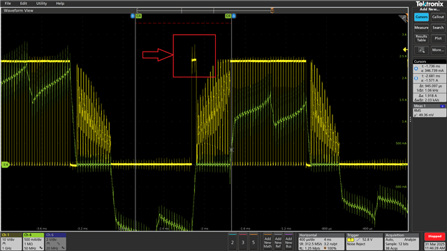
When the next quadrant is to take over, the sinking (commutation) FET turns off (say phase C), its high side FET body diode starts freewheeling, then after a small software delay we turn on the FET of the next sinking pole/phase (say phase B). During that time, the sourcing pole (say phase A), while totem pole A is complimentary switching high FET - low FET (avoiding a shoot through switch sequence), then WHEN the sourcing totem (pole A) switches from "low on - high off" to "low off - high on" at phase C that was on and now its off (across the low FET) a transient appears of 20nsec duration that is ~7V above the bus. The transient is 100% correlated with the PWM-ing.
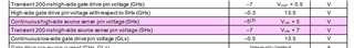
Whatever we do, the transient seems to never go over ~55V It can go lower, with different motor currents and with slowing the gates current (IDRIVE) but seems very strange that that limit exists !!
One thought is that the DRV has some mechanism of shunting transients on the phase lines of VM+7V (55 in our case). Or something similar?
We have to slow down the gate charge, because 55V is very close to the 60V maximum FET Vds. We are ready to launch the product, and changing the FET is not an option.
Attached is an image where the transient appears twice,