Other Parts Discussed in Thread: DRV8889-Q1,
Tool/software:
Hi Team,
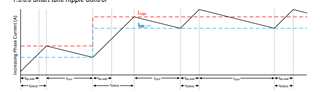
Could you tell me sequential of setting Ivalley at Smart tune Ripple Control Decay Mode?
Especially, Customer want to know about relation between Itrip and Ivalley.
Please provide some material if we have.
Best Regards,
Yusuke