Tool/software:
Hi Expert,
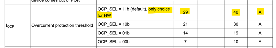
As the title, how to set the overcurrent value to 29A?
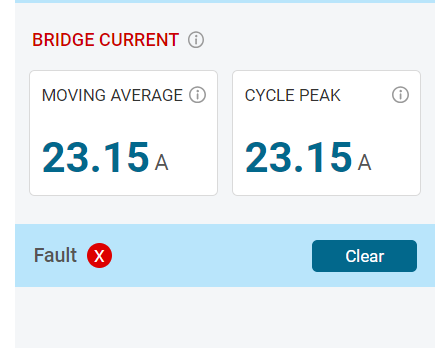
The output current is about 23A.
Thanks a lot!
Andy
Tool/software:
Hi Expert,
As the title, how to set the overcurrent value to 29A?
The output current is about 23A.
Thanks a lot!
Andy