This thread has been locked.

If you have a related question, please click the "Ask a related question" button in the top right corner. The newly created question will be automatically linked to this question.

DRV8353: Charge Pump

Part Number: DRV8353

Tool/software:

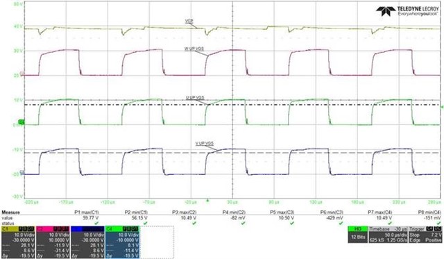
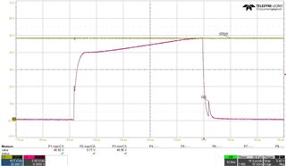
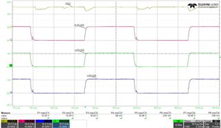
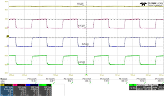
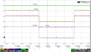
Customer found the dropout voltage on the VCP pin when operation as below CH1 probe. 

Condition:

- PWM Freq: 10KHz

- Qg total,max : 1128nC

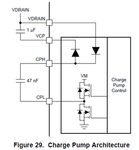
- Following d/s to put 1uF between VDRAIN and VCP, and 47uF between CPH and CPL

Question:

1. How is the capability of the charge pump? is that able be controlled?

2. If both 1uF or 47uF are increased, is that able to improve the dropout of the VCP? What max. recommended capacitance you suggesting?

3.  How much MOSFET's Qg you suggest to drive with DRV8353?

  • Hi Brian,

    Can you please provide the datasheet for the MOSFET being used? 

    I would also like to know how many FETs are switching during commutation? (Trapezoidal or FOC commutation).

    With this information, I should be able to calculate this for you regarding DRV8353

    Thank you,

    Joseph

  • Hi Joseph

    The MOSFET is Infineon-IPTC014N08NM5. and we used two MOSFETs per phase during FOC commutation.

    The waveforms are measured at Zero Sequence. which means the DRV8353 is driving six MOSFETs at same time.

    we can find that Vgs is not perfect square wave.

    so,we would like to know 

    a. The capacitance between VDRAIN and VCP, increase to 4.7uF or more. is it okay for DRV8353

    b. The capacitance between CPH and CPL, we increase to 100nF or 470nF. would like to improve VGS but it didn't help.(just reduce switch times). is it good for increase the capacitance?

    c.base on our situation,DRV8353 Tcase max. 120°C, is it okay?

    d. about VGLS at Zero Sequence, the voltage have three Volt drop,and VGS is near square wave (VGS =10.5V). it is okay if increase the  VGLS external capacitance to reduce drop.

    Sincerely yours,

    Bevis Lin

  • Hi Bevis,

    We always recommend using the capacitor values for VCP and CPH CPL as stated in the datasheet. 

    The non perfect square waves I believe are being caused by the dips in your VCP. 

    Can you check if the voltage waveform dips also happen in Vdrain? 

    On your board, are VCP, CPH, CPL capacitors placed near the device?

    Thank you,

    Joseph

  • Hi Joseph,

    The Vdrain dip didn't happen like VCP. 

    About VCP,CPH,CPL capacitors, there are placed near the SGD.

    we also check the VGLS, it has happen dip,too. the VGLS capacitor is 1uF.

    Therefore,We would like to add capacitor to reduce the voltage dip.

    The following waveforms can show that adjusting VCP capacitor to 4.7uF and VGLS capacitor to 4.7uF are good way to fix the problem.

    please let us know what the risks are.

  • Hi Bevis,

    Thank you for all of the information. I'm glad the change from 1uF to 4.7uF helped solve the VCP dip problem.

    Here is one thing to keep in mind: The higher capacitance value takes longer to discharge and therefore solves the voltage dipping problem you saw on VCP. This also means that the capacitor will take longer to charge. However, your waveforms look much better now and this shouldn't be an issue in your system.

    Here is one thing that maybe caused this with the previous 1uF cap. What was the voltage rating on the capacitor? And how much voltage was it seeing in your system. For example, a capacitor rated for 16V that sees ~15 to 16V could potentially have its effective capacitance reduced by anywhere from 30-60%. This is why it is recommended to use capacitors rated for voltages around 1.5x to 2x what the node will see. 

    I'm glad I could help solve your issue. Let me know if this problem is resolved and I can go ahead and close the thread.

    Thank you,

    Joseph

  • Hi Joseph,

    For VCP / VGLS capacitor, we choose 4.7uF/25V. Thanks for your support and reminder.