Tool/software:
[Question]
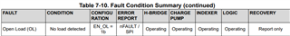
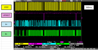
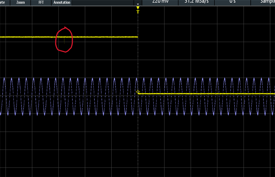
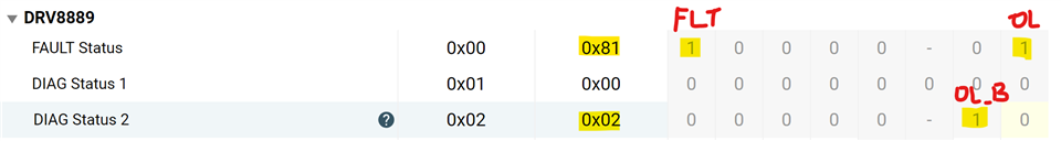
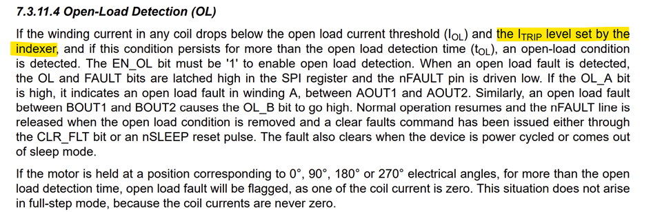
For Open Load detection.
Is it possible that nFAULT pin does not indicate the error(Low) while there is Step signal if Motor is set to Open?
Fault is only detected if there is no Step signal?
Tool/software:
[Question]
For Open Load detection.
Is it possible that nFAULT pin does not indicate the error(Low) while there is Step signal if Motor is set to Open?
Fault is only detected if there is no Step signal?