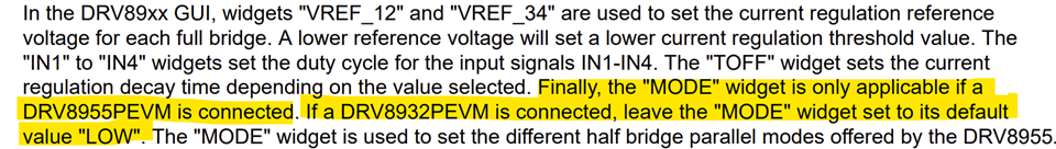
Other Parts Discussed in Thread: DRV8935
Tool/software:
Dear TI team,
I’m using the DRV8935 EVM and have some questions regarding its compatibility and configuration when driving a unipolar stepper motor.
-
The motor is a unipolar stepper type. Is it suitable to drive it using the DRV8935 EVM? If needed, I can share the datasheet with you privately for confirmation.
-
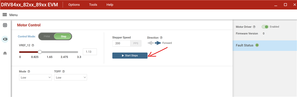
In the EVM GUI, the green circled section appears to be for setting PWM – is this correct?
For the red boxed inputs IN1 to IN4, how should these be configured to drive the motor properly?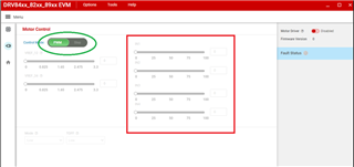
-
I tried selecting “Step” in the green circled area. The motor coil center tap was not connected to any voltage, and the motor was able to operate after starting. This seems like the CPU is simulating a bipolar drive method. However, since the selected device is DRV89xx, which theoretically does not match this drive method, why is the motor still able to operate?
-
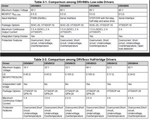
The attached file mentions two unipolar driving methods: Low-Side Drivers and Half-Bridge Drivers.What are the main differences between these two methods?
Thank you for your support!