This thread has been locked.

If you have a related question, please click the "Ask a related question" button in the top right corner. The newly created question will be automatically linked to this question.

MCF8316C-Q1: Communication Issues with MCF8316C-Q1 via USB-8452 and LabVIEW

Part Number: MCF8316C-Q1

Tool/software:

Dear Texas Instruments Support Team,

I hope this message finds you well.

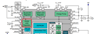
I am currently working on a project involving the MCF8316C-Q1 motor driver, which is implemented on a PCB designed by one of our clients. I am experiencing difficulties establishing communication with the device in order to read and overwrite some incorrectly programmed registers.

I am using LabVIEW in conjunction with a USB-8452 SPI interface, but so far I have been unable to successfully read from or write to the MCF8316. I suspect I may be missing a required step or configuration, but after several attempts, communication has not been established.

Could you please provide some guidance or recommendations for interfacing with the MCF8316C-Q1 via the USB-8452? Any documentation, reference code, or configuration tips would be greatly appreciated.

Thank you very much for your time and support.

  • Hi Adriana,

    Thanks for reaching out. The MCF8316C-Q1 has an I2C interface, not SPI. There is not guide specific to the USB-8452, but you can refer this appnote which discusses how to program I2C for the MCF devices.

    Regards,
    Sachin S

  • Could you please clarify how I can correctly perform a read operation to identify the TARGET ID or device address over I2C? I have attempted communication using various addresses but have not received any response from the device.

    Additionally, I would like to ask whether the device requires any specific procedure to wake up. I am wondering if it might be in a low-power or sleep mode, which could explain the lack of response to my I2C commands.

  • Hi Adriana,

    Could you check the DVDD voltage and let me know if you are observing 1.8V?

    Regards,

    Sachin S

  • Hello Sachin,

    I don’t have 1.8V, in fact, I have more. I supplied 13V, and on DVDD and AVDD, I see much higher voltage than what the datasheet specifies.
    What does the output of DVDD and AVDD depend on? Aren’t they fixed outputs? Are they expecting to detect a motor?
    And how should the BRAKE and SPEED pins be configured?

    I appreciate your support.

  • Hi Adriana,

    The health of AVDD ensures the internal LDO on VM is functional. And DVDD voltage is critical as it powers the whole digital circuit of the IC. Typically DVDD is extracted from the FB_BK (buck converter output). How is your design implementation? Could you share the schematics for me to review?

    Also please do refer this application note on designing for MCF8316C.

    Regards,

    Sachin S

  • Hello Sachin,

    I'm sharing part of the schematic for you to review and let me know if you notice anything unusual. The issue only occurs when I try to communicate with the MCF8316C-Q1, regardless of whether it is pre-programmed or not.
    The circuit is implemented on a client's board, and they made a mistake when writing the parameters. As a result, I need to overwrite the information, which is why I require communication with the circuit.

    I appreciate your feedback.

  • Hi Adriana,

    I think the design looks okay. Could you share your I2C implementation.

    And how should the BRAKE and SPEED pins be configured?

    SPEED pin should be set at a non zero voltage just to make sure the device doesnt enter sleep. BRAKE can be set to anything.

    Regards,

    Sachin S