Other Parts Discussed in Thread: DRV8256
Tool/software:
Hello. I'm using the DRV8256PEVM, hooked up to an MCU that is driving the IN1 and IN2 inputs. My motor is actually a 2.8 ohm resistor, which is what our application needs (bipolar drive across a 2.8 ohm resistive load).
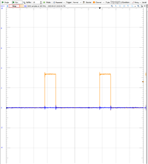
Right now, for the most basic test, IN1 is pulsed at 20% duty cycle (25kHz frequency) and IN2 is low, as shown below.
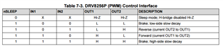
I would expect the motor voltage to follow the truth table of Table 7-3, being in Brake for 80% of the period, and Forward for 20% of the time.
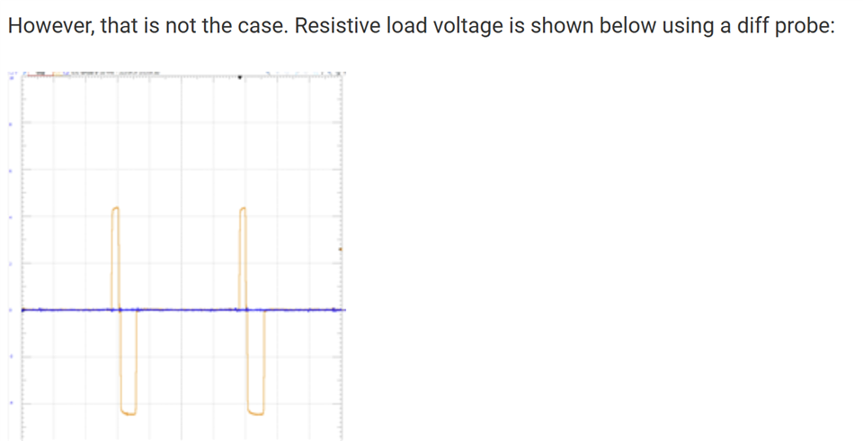
However, that is not the case. Resistive load voltage is shown below using a diff probe:
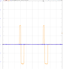
Where VM=5V. So +5V for ~10% duty cycle and -5V for ~10% duty cycle. Why is this the case? It seems to violate the Table 7-3 Truth Table.
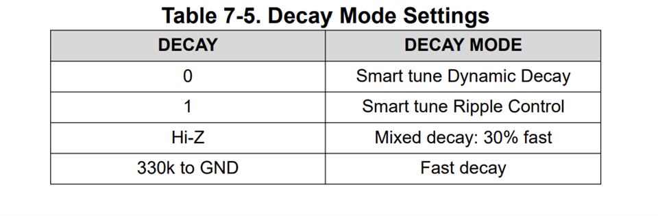
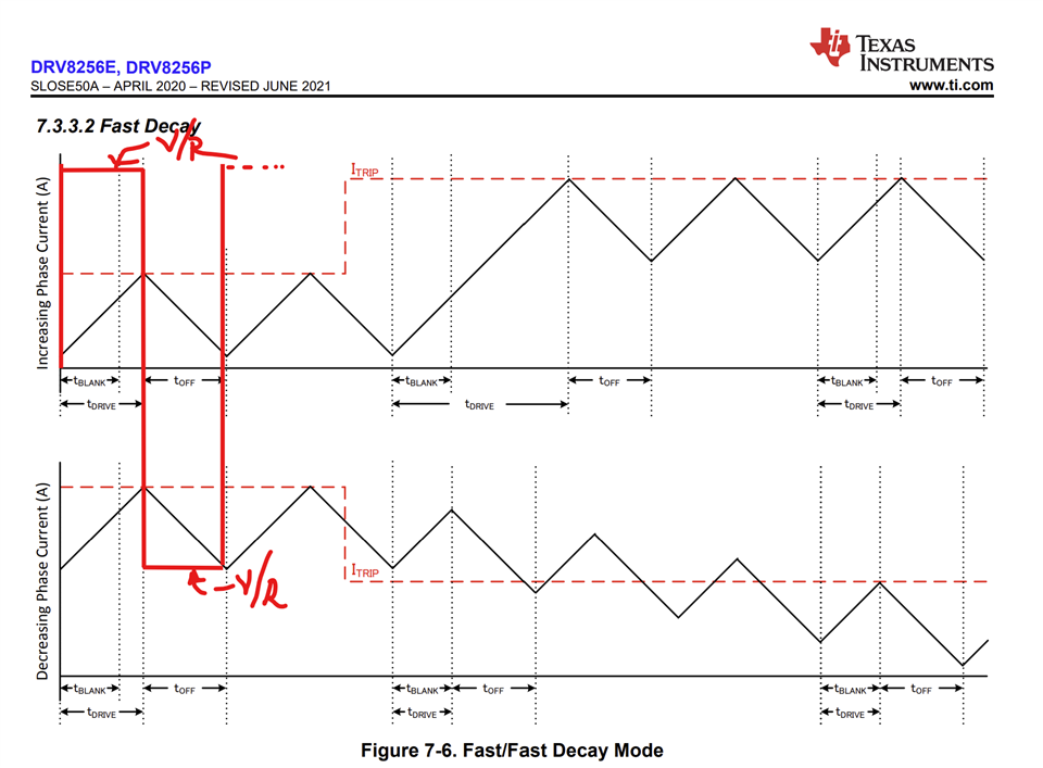
Am I missing something regarding the operation of this motor driver IC? Could it be related to Decay Mode?
Thanks,
Rob