This thread has been locked.

If you have a related question, please click the "Ask a related question" button in the top right corner. The newly created question will be automatically linked to this question.

DRV8220: MCU resets when driving a solenoid latch valve

Part Number: DRV8220
Other Parts Discussed in Thread: BQ25892

Tool/software:

Greetings to all.

Sorry for the delay, but the new boards have finally arrived, and I was able to test them. I see that the original post has been blocked, so I'm creatings this related question. I don't know if I need to re-write the context, please let me know if it's needed. First I'll comment what changes I did to the board, and then the results of the tests.

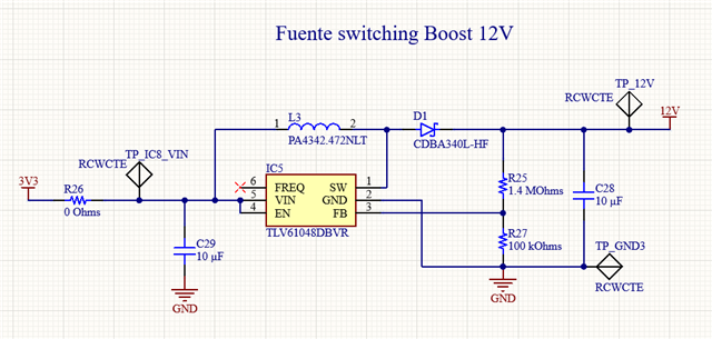
Regarding the changes, what I did is change the 12 VDC power supply. I chose the TLV61048DBVR from TI, which has a peak switching current limit in between 2.9 and 4.5 A:

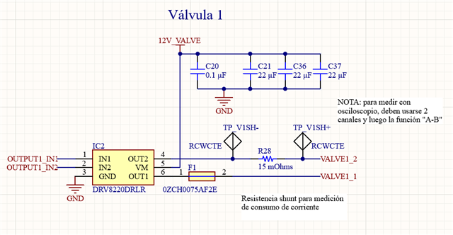
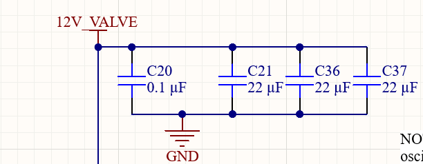
In addition, as Jacob suggested, I added a series of capacitors to each output, for a total value of 66 uF:

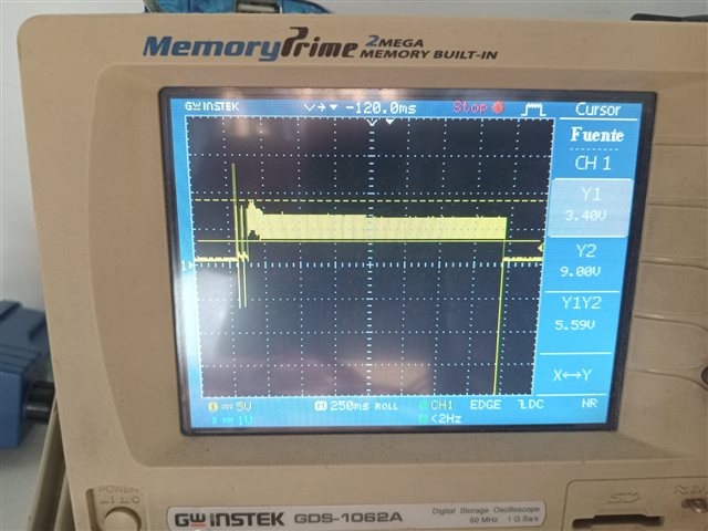
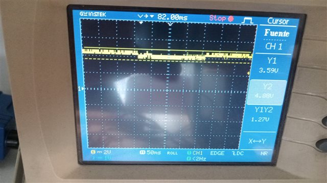
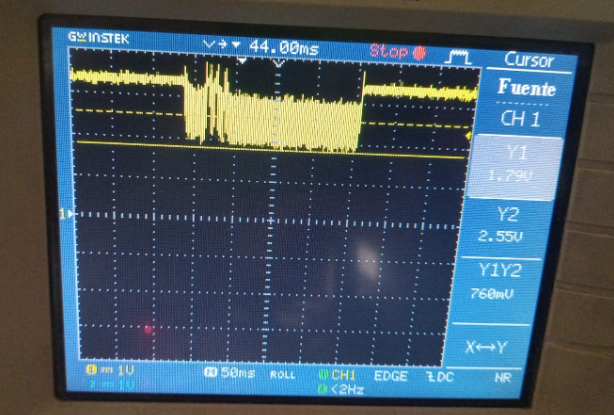
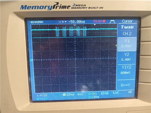
Now, regarding the results, sadly, they remain the same. The ESP32 still resets. I was able to see the voltage drop in the 3V3 line when the valve is triggered:

As you can see, the voltage drops below 1V.

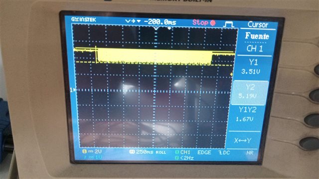
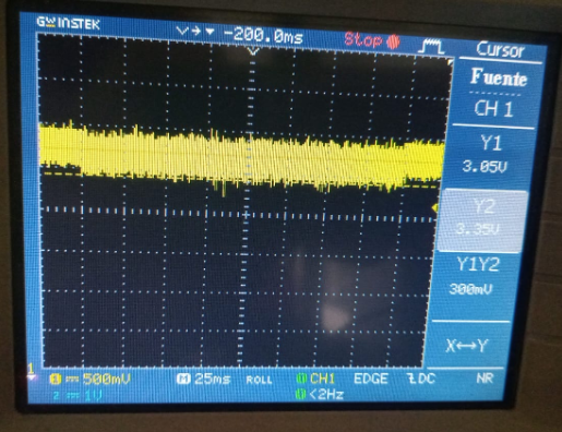
Then, what I did Is try to isolate each power supply, so I could find which one is failing. First, I powered the board with 4V between the output of the battery charger and the input of the 3V3 power supply, and tried to trigger the valve. And with that test, the valve was able to open without causing the ESP32 to reset. This is what I saw in the 3V3 line:

As you can see, although there's a voltage drop of around 500 mV, it doesn't drop below 1V as before.

What I get from this test is that the problem should be in the battery charger IC, which is the BQ25892 from TI. But the things is that that IC, at least according to its datasheet, can support of to 5A of switching current, a value well above the one that the valve requires to switch. I know that that IC has some current and voltage configurations, such as the maximum allowed switching current, but I've checked those values, and the ILIM current is set to 3.25 A, and the VREG voltage is set to 4.208 V, so I would say that that's not the problem.

Any ideas of what could be wrong? Thank you.

  • Franco,

    Can you post your full schematic?

    Are you using the BQ2589x as an LDO or buck converter to generate the 3.3V logic voltage? Seems like that would be better served by an LDO or a buck converter, the BQ25892 is a battery charger so it might be tripping or throwing warnings if it senses its load is not a battery.

  • Greetings Jacob.

    Thank you for your help. Regarding the SCH, due to company policies, I can only share the parts of the SCH that are related to this issue, not all the board. So, here are the SCH of the battery charger, 3V3 power supply, 12V power supply and valve controller circuit:

    -Battery charger BQ25892:

    -3V3 power supply:

    -12 V power supply:

    -Valve controller:

    I apologize because there are some parts that are in spanish (I'm from Argentina).

    Regarding your 2nd question, I'm using the BQ25892 as a switching power supply and to charge the battery, so it generates 4.2 V which then powers the 3V3 Buck-Boost power supply, which then powers the 12 V Boost power supply. From what I understood, the BQ25892 can be used to power a load different from a battery, or maybe I'm mistaken. Or could be that there's some internal register to configure this case?

    On the other hand, I made some more tests. What I did is put a 470 uF capacitor in parallel with the output of the battery charger, and then power the input of the battery charger with my lab power supply. In this case, when I try to switch the valve, it works. So, with this test and all the previous tests that I've made, I think that the problem is that the battery charger is not supplying enough current to the load in the transients that occur when the valve is switch.

    Any suggestions?

  • Hi Franco,

    Sorry for the delay. Please allow me some time to review the schematic and I'll provide feedback tomorrow. 

    Best,

    David

  • Greetings David.

    Sure, no problem. Will wait, and thank you.

  • Hi Franco,

    This seems more to be an issue for the battery management team. Let me transfer you to them for further suggestions.

    Best,

    David

  • Greetings David.

    Understood. Then, should I close this post an re-open it in the "Power management forum"? Or is that not necessary? Let me know.

  • Hi Franco,

    David has looped us in to this thread. Your schematic looks fine. If I understand correctly the VIN_BB Net is likely connected to the VOUT_BTY_CH Net on the BQ device schematic. This would be a fine implementation.

    The BQ is able to source the required, the ISYS output current has a 5A current limit which should be able to provide current as needed. As you said the issue may lay in the transient response since it looks like the current load is applied very quickly. In this case the voltage drop may be due to the delay in loop response as current is quickly pulled out of the SYS capacitor. In these scenarios, it's typically recommended to increase SYS capacitance, VIN capacitance, or VBAT capacitance to provide a larger reserve to pull current from, without reducing voltage. Can you provide a waveform of the load pulses including VIN, SYS, and BAT?

    Do you see these current pulses when powered from both VIN and Battery? Or are they not seen when battery operated?

    Best Regards,

    Juan Ospina

  • Greetings Juan.

    Oh, I see, so I understand that you are saying that the problem is that the BQ isn't able to provide enough current in the transients only, and that could be solved with more capacitance, right?

    Regarding the signals, I've aquired some pictures of them. And yes, the problem arises when I use the BQ alone, with no battery connected. So, I will split the signals into those where there's no battery and those where I put the battery:

    NO BATTERY:

    -LOAD:

    -VSYS (which is basically VOUT_BTY_CH):

    -VIN:

    WITH BATTERY:

    -VBAT:

    -LOAD:

    -VOUT_BTY_CH (basically VSYS):

    So, as you can see, the signals are quite normal when the battery is connected. According to what you said, this could be because the battery is acting as a capacitor in the transients, providing the needed current to switch the valves.

    However, I think that it would be great if the circuit worked even without the battery connected. So, for that case, what do you suggest? To add more capacitance in which places? And what values do you suggest?

    Best regards,

    Franco.

  • Hi Franco,

    I didn't realize the issue was present while the Battery was not connected. If battery is not connected the output voltage of the charger is limited by the input current of the VBUS source, which as you mentioned is set to a maximum of 3.25A. This might be enough depending on the input voltage, higher input voltages allow the output to reach higher currents even given a 3.25A input current limitation. The input current limit might be reduced by protection measures such as VINDPM. Do you have a capture of VBUS in a no-battery setup when the load is applied?

    Best Regards,

    Juan Ospina

  • Greetings Juan.

    Oh, I see, I didn't know that if you supplied more input voltage, the current limit incremented. In my case, I'm powering the circuit using a lab power supply, set to 5V. And I would say that yes, the current consumed by the valve should be way lower than 3.25 A.

    Regarding the VBUS signal, yes, it's on my previous comment, the image in the "NO BATTERY" section named "VIN". Just in case, here it is:

    Best regards,

    Franco.

  • Hi Franco,

    Sorry I must have missed that. It looks like the load seems to be too much for your input source based on the voltage dips. The voltage of VIN seems to be dropping to levels in which it would trigger VINDPM or sleep, the device wouldn't be able to pull more current from the input once VIN has dropped a significant amount. If your input source should be able up to 3.25A of output current then it might transient response limitations on the part of your input source This can be mitigated by increasing the VBUS capacitor. If your lab power supply has a current limitation below 3.25A, you can try increasing this setting, or using a more powerful input source if it is maxed out. This should confirm that is the cause of the behavior we're seeing.

    Best Regards,

    Juan Ospina

  • Greetings Juan.

    Oh, I see. Well, my lab power supply can provide up to 5.1 A, and it has an overcurrent protection that is configurable. So I just changed that value to the maximum of 5.1 A, and tried to switch the valve, but it still resets the ESP32. You think the transient current is going higher than 5.1 A? 

    Regarding the VBUS capacitors, do you have a value suggestion? Maybe I can increment the output capacitors too. I can add that I've tried with a 470 uF capacitor in several places of the circuit, just as the output of the battery charger, output of the 3V3 power supply and input of the 12 V power supply, and in that case it worked. I chose that high value because I've seen some latch valve designs that use a 4700 uF capacitor, which seemed a lot to me. But in my previous post, Jacob suggested that that high value capacitor is only used if the power supply can't provide enough current, and if I sized the power supply correctly, it wouldn't be necessary.

    Best regards,

    Franco.

  • Hi Franco,

    I see, that does seem like sufficient power so its unexpected that VIN would drop so significantly. It seems like there are two possible causes:

    1. Resistance in the line between the supply and the VIN pin could cause the voltage to drop as current increases. Decreasing the resistive load between the two might improve performance.

    2. As mentioned this could be related to transient behavior in which case capacitance does help on any point along the power-path or throughout the power-path. Unfortunately I can't recommend a particular value as I'm not really familiar with the load devices. One thing to keep in mind is capacitance derating at higher voltages, its important to keep that in mind when selecting your components.

    Best Regards,

    Juan Ospina

  • Greetings Juan.

    Regarding the first point, I would say that, although obviously there's resistance between the input in the board and the input pin of the BQ, it's in the order of a few mOhms, because the distance is around 2 cm. So I think that wouldn't cause the voltage drop of hundred of mV that I'm seeing.

    Regarding the second point, I see. I think that, given that the switching of the valves is what generate the need of current in the transient, maybe the capacitance should be placed in the 12 V power supply, which powers the valves. But I'm still confused as to why if I sized all the power supplies correctly, according to the current that the valves seem to consume in the transient when they switch, there's still a voltage drop. Because, compared to the previous version of this board, I also added some extra capacitance, for example, around 60 uF next to every valve. But I don't know, maybe the peak current is higher than I think, and that's why in the designs that I saw in the internet they put that large capacitor of 4700 uF. The problem is that that capacitor is huge in size, so that's why I wanted to avoid it.

    Best regards,

    Franco.

  • Hi Franco,

    Regarding the first point, I would say that, although obviously there's resistance between the input in the board and the input pin of the BQ, it's in the order of a few mOhms, because the distance is around 2 cm. So I think that wouldn't cause the voltage drop of hundred of mV that I'm seeing.

    In this case the resistive path isn't necessarily the cause for the voltage dips.

    Regarding the second point, I see. I think that, given that the switching of the valves is what generate the need of current in the transient, maybe the capacitance should be placed in the 12 V power supply, which powers the valves. But I'm still confused as to why if I sized all the power supplies correctly, according to the current that the valves seem to consume in the transient when they switch, there's still a voltage drop. Because, compared to the previous version of this board, I also added some extra capacitance, for example, around 60 uF next to every valve. But I don't know, maybe the peak current is higher than I think, and that's why in the designs that I saw in the internet they put that large capacitor of 4700 uF. The problem is that that capacitor is huge in size, so that's why I wanted to avoid it.

    Unfortunately, I'm not familiar enough with your application's load characteristics to comment. Ultimately, its possible that the source and charger are able to provide the power as needed in a DC level or with slower transients but the transient behavior and in-rush current may have an impact that would need to be examined. The VIN waveforms you provided tell me that the input source isn't able to keep up with the rapid current draw so the capacitance may be necessary to provide current to pull from, the best place to place that capacitance will be dependent on your application's specifics.

    Best Regards,

    Juan Ospina

  • Greetings Juan.

    I understand. Then, I will try with some values of capacitance, and put the capacitors close to the root of the problem, which are the valve, so probably in the output of the 12 V power supply. Thank you very much for your help.

    Best regards,

    Franco.

  • Greetings Juan.

    Sorry, I'm posting again because I've made some test, and seem to have found the final solution. Sadly, I can't mark this reply as "This resolved my issue", but well, hope it helps anyway.

    First, I bought a 2200 and a 4700 uF capacitor (35 V both). Then, I soldered them in different places of the power line of my board, and testes the results when switching the valve. I was hoping that, with such a huge capacitor of 4700 uF set in the 12 V line, the problem would be fixed, because it could provide the current needed by the valve in the transient. But, although in some cases the ESP32 didn't reset, the truth is that, watching for example the 3V3 line, I was still seeing a considerable voltage drop, of about 1 V. Here's an example:

    In this case, the battery was connected, and I was powering the board with my lab power supply, with 5V.

    Then, I thought: "well, maybe the real solution would be to mitigate the peak current in the valve, which is the real cause of this problem". So I thought I could add a resistor in series with the valve. I first tried with a 100 Ohm resistor, but with that value, the valve couldn't even get enough current to switch correctly. So then I tried different resistance values, with the help of a potentiometer, and, for example, with a value of 25 Ohm, the valve seemed to switch correctly, and the voltage drop nearly dissapeared. Here you can see the 3V3 line:

    And here the 12 V line:

    So, in conclusion, I think I will just add a series resistor to each valve. I'm still curious about why the huge capacitor didn't work as intended though.

    Best regards,

    Franco.

  • Hi Franco,

    A current limiting resistor makes sense as a potential solution if peak current is the issue with this load profile.

    I'm still curious about why the huge capacitor didn't work as intended though.

    To identify this I would look into where along the power-path you would see the initial voltage dips and where the capacitors were placed. Its important to note that if they were placed somewhere away from the source, they would increase inrush current since they require a lot of current to get charged up to that point. This might not be a factor if the capacitors are already charged up when you enable the load, that scenario they should have helped to resolve the issue by providing a large reservoir of charge from which to pull. 

    I think an analysis of what your load profile looks like (including load slew rate), what your current limitations are at each step, and the bandwidth of the control loops of the devices in your power path would help you narrow down a root cause as to limiting factors in sustaining a correct voltage. That isn't necessarily an easy investigation.

    Best Regards,

    Juan Ospina

  • Greetings Juan.

    Well, in some of my tests, I even put the 4700 uF capacitor next to the 12 V power supply, and at the same time, the 2200 uF in the 3V3 line, close to the VIN pin of the ESP32, and even in that case, I saw that voltage drop of around 1 V that I showed. And yes, the capacitors should have been charged before switching the valves, because there's a delay between each switch of several seconds, and I think those capacitors would need a few ms to charge.

    Regarding the analysis that you commented, yes, I agree that it woulnd't be easy at all, given that I did several tests, in which I measured all the important signals of my board, and even with all of this, I still can't figure out why that voltage drop happens. Maybe it could be a noise related issue, because I'm powering the ESP32 with the same power supply with which I'm powering the 12 V line, which powers the valves. Or maybe I should've used a linear power supply to power the ESP32 instead of a switching power supply, because I think that they are more stable regarding transients.

    But well, in conclusion, given that I don't have more time to do tests, and I think with the resistors in series with the valves the problem shouldn't happen again, I think I will just go with that, and live with the torment of not knowing the answer to that question Grin

    I hope this helped someone.

    Best regards,

    Franco.