Tool/software:
Hi,
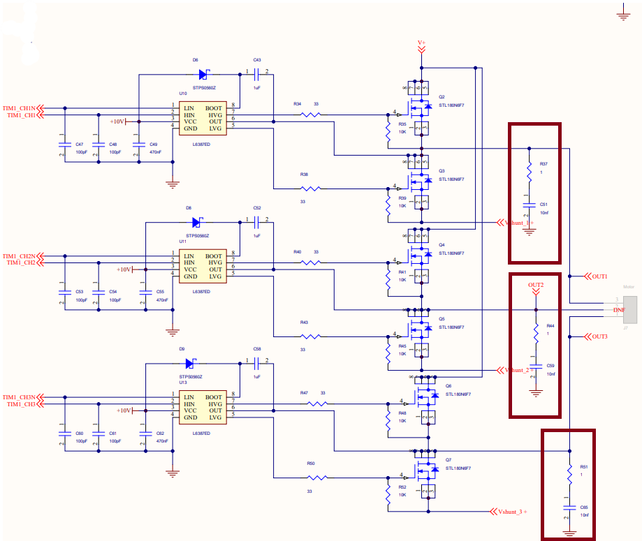
I have notices in majority of motor controllers, developers have added resistors and capacitors in the output of each phase, in FOC BLDC motor controllers.
Can you help mw with this, how do I calculate those. Why and where to place those in my driver circuit.
In the below circuit i have highlighted the resistors and capacitors placed in the output and below that I have shared my schematic for LMG2100R026. Kindly look into it.
Regards,
Madhav Parashar