Other Parts Discussed in Thread: MSPM0G3507-Q1
Tool/software:
I am trying to use the DRV8000Q1 EVK as an edge node to drive a motor via the H-Bridge gate driver.
I tried to configure the EVK for this using the TI GUI, but I am seeing ~0V from the H-Bridge output (J4). All the jumpers are present on J1 and J2, as it came out of box.
For this thread I am not even talking about connecting the EVK to the controller MCU; I am simply connecting the EVK to my PC and probing the H-bridge gate driver output with a DMM, after loading the register config.
Below are the steps I tried:
1. Supply 12V to 'VBATT' on the DRV8000Q1. No under voltage warning in the GUI, so this seems fine.
2. Update DRV8000Q1 with latest firmware ('File' -> 'Update EVM Firmware').
3. Enable the H-bridge gate driver by writing to 'GD_CNFG' register. I am able to read in the GUI that the enable bit is set.
4. 'File -> Save Registers'
5. 'File -> Load Registers'
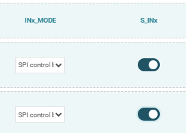
6. Supply an input to the H-Bridge from the MSPM0G3507-Q1 MCU on the EVK. In 'External Control (MCU)', I've configured 'GD_IN1' with the following settings:
Duty Cycle 50%, PWM Frequency 20000, Ramp Rate 10, Ramp start.
7. Measure gate driver output voltage.
I have tried various other configuration settings, specifically in 'GD & CSA controls', but nothing I tried was successful. Also tried various writes to GD registers. Made sure to save + load registers every time I made a change.
For just getting the gate driver output enabled with the 'External Control (MCU)', do I need to configure the GD inputs and/or operating mode?
1. I have tried this already with no success.
2. I don't see why I would need to, please help me understand why if I do in fact need to.
Do I need to remove the jumper on DRVOFF pin? The user manual for the EVK says to leave it on when using the GUI. Are there any jumpers I need to remove?
Or what else am I missing in the configuration?


 set EN_GD
