Tool/software:
Hi team,
My customer is evaluating DRV8889-Q1 and meets the step loss issue, could you please help give some suggestions? Thanks.
1. Could you help share what might be the potential causes of step loss?
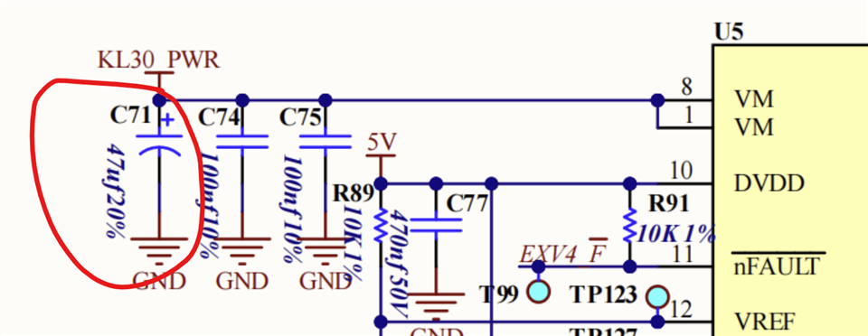
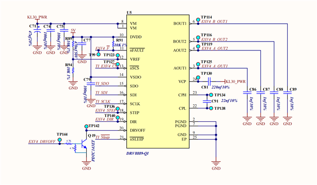
2. The following is customer's schematic, could you help review and give some comments?
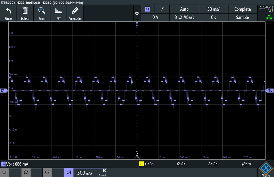
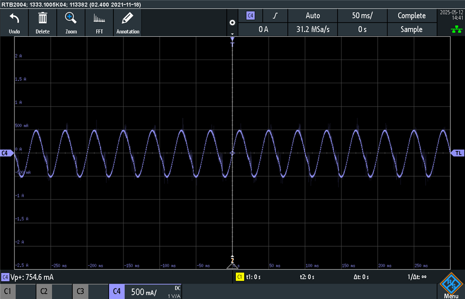
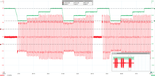
3. In testing, the customer found that when the DRV8889-Q1 is configured as 1/2 step, the output phase current varies significantly between VMs, as shown in the following figure. However, when the DRV8889-Q1 is configured as 1/16 step, the output phase current value is basically the same for different VMs. May I ask that why is that? Theoretically, the output phase current should be independent of VM.
DRV8889-Q1 schematic:
1/2 step, VM=9V or 16V, the green waveform is VM, the red waveform is output phase current.
Regards,
Ivy