This thread has been locked.

If you have a related question, please click the "Ask a related question" button in the top right corner. The newly created question will be automatically linked to this question.

DRV8870: Slow rise in output waveforms

Part Number: DRV8870

Tool/software:

Hello,

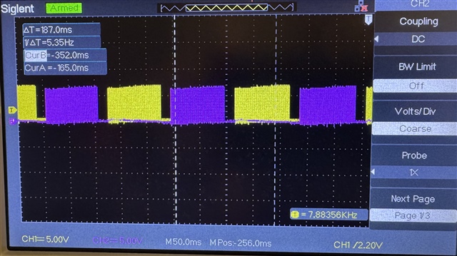
I've designed a motor driver around the DRV8870 driving a this DC gearmotor. Stall current is 2.2A. I'm trying to drive it back and forth with 100% PWM with no attached load, but when I measure the two motor terminals with respect to ground I am seeing the current slowly rise but never reach the supplied 7V. I see very little noise on the supply voltage which makes me think this has something to do with the motor driver.

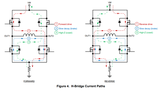
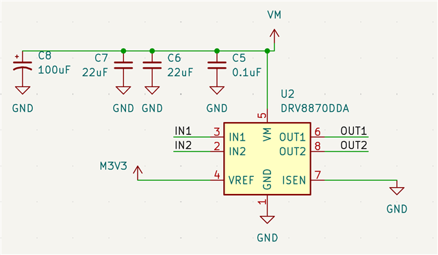
Here's a schematic of the design. I originally had a 0.15ohm resistor between ISEN and GND, but removed it because the motor required more than 2.2A to switch directions. Out1 and Out2 go directly to the motor terminals.

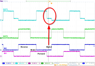
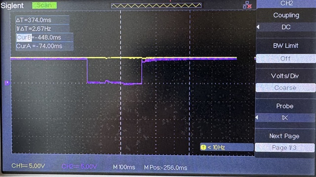
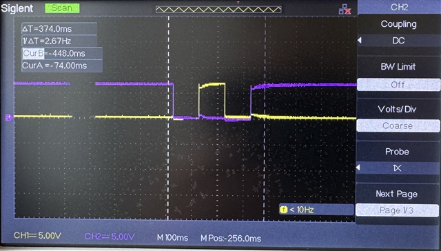
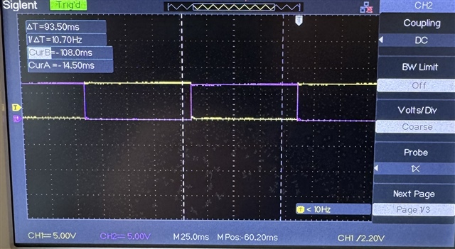
I've also verified that this motor works with a different, 7A, motor driver board when supplied the same IN1 and IN2 voltages. Here's what the the two motor terminals measure with the other motor driver. The inputs are switching directions every 100ms, vs. the 100ms forwards + 1000ms reverse in the first image.

Any ideas why the DRV8870 is not working for this application?

  • Hello,

    It's possible that while switching directly from a forward to reverse state the current through the motor doesn't have time to recirculate before switching directions. There's an automatic dead time (tDEAD=220ns) to prevent shoot-through. It's possible the "noise" you are seeing could be because of this. 

    If possible, I would suggest entering a brake state (slow decay) in between forward and reverse. This should allow the current to recirculate through the low-side FETs between switching directions. 

    Best,

    David

  • Thanks! I tried adding a brake state by driving both input pins high between the forward and reverse, but that did not change the output waveforms.

    Left is one of the motor terminal in purple and Vmotor in yellow, right is both motor terminals.

    I also noticed the concerning behavior when running the motor at 60% PWM duty cycle, where I'd assume the off times would also help provide time for the current to recirculate.

    Left and right images both have the left and right terminals with the same 100ms forward, 20ms brake, 100ms backwards, 20ms brake inputs, just very different timescales so you can see the similar slow rise of the peaks of OUT1/OUT2 in the first image and OUT1 being nonzero voltage while OUT2 is being driven in the second image.

  • Hello,

    What supply are being used for these tests? If a power supply on the bench, is the current limit on the supply set high enough?

    It looks like the variations in the output voltage are following VM supply.

    Best,

    David