


Tool/software:
Good morning,
We have encountered a driver overheating problem, especially when the PWM signal duty cycle is between 30% and 90%.
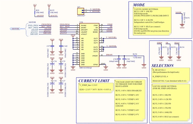
The driver is configured in mode 3 (full bridge) and is driven by PWM at 10 kHz. The outputs are connected directly to the motor.
Analyzing the two outputs with the oscilloscope, we noticed that, during the periods in which the PWM signal is low (0) (the other pin is always at 0), both outputs are active towards the positive. We believe that this condition is the main cause of the driver overheating.
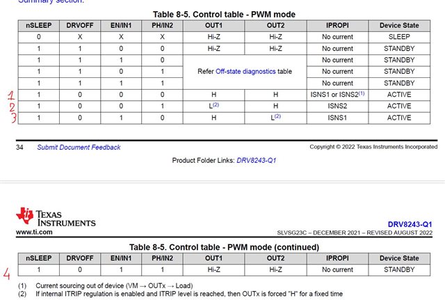
Consulting the datasheet, in particular Table 8-5 "Control table - PWM mode" (see attachment), we observe that, when both inputs are at 0 (case 1), the outputs are both high. To avoid this condition, we tried to keep a constantly high input, so that with both inputs at 1 (case 4) the outputs are in high impedance. However, we did not obtain the desired effect: instead we detected an alternating square wave.
Our need is to avoid overheating of the driver and we do not need the motor brake function.
What configuration do you recommend to obtain a correct behavior without incurring the heat dissipation problem?
Best regard
