Tool/software:
Hi Sir,
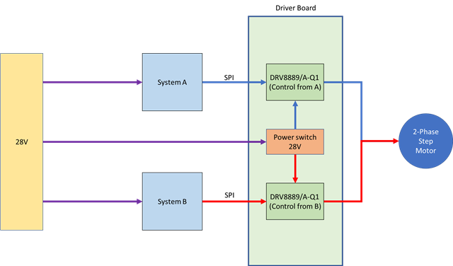
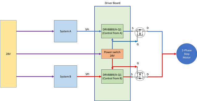
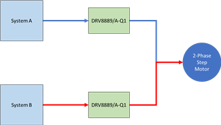
We have a stepper motor design that requires a redundant system. I would like to ask if it is possible to connect two DRV8889/A-Q1 drivers—one from system A and one from system B—to the same motor.
Systems A and B will not operate at the same time.
What kind of issues might this cause? For example, could the current from system A's DRV8889/A-Q1 backfeed into system B's DRV8889/A-Q1?
thanks