This thread has been locked.

If you have a related question, please click the "Ask a related question" button in the top right corner. The newly created question will be automatically linked to this question.

ULC1001: relationship between temperature and LCS impedance

Part Number: ULC1001

Tool/software:

Hi team

In the technical manual of ULC1001, the temperature calibration needs to obtain a linear relationship between temperature and LCS impedance.

Can the ULC1001 chip measure this impedance value?

The function of the USER_Params_tempParams_slope_CperOhm_Q27 register of ULC1001 is to set the slew rate parameter between LCS impedance and temperature.

I would like to ask whether this parameter value is obtained through actual measurement or a value obtained after internal calibration of the ULC1001 chip?

Thanks~

  • Hello,

    This slope parameter needs to be calculated and set prior to calibration. Essentially you need to collect various data points of the LCS impedance at various temperatures (at one frequency). It can be calculated by measuring the impedance of the LCS using an impedance analyzer while set in a temp chamber for various temperatures.

    If you do not have an impedance analyzer you can use the ULC calibration feature just as a method of measurement since ULC1001 can calculate impedance. To do this you can have the LCS in a temp chamber, set the region 1 calibration burst frequency range to the temp calibration frequency (should be away from resonance), and run this burst to populate the impedance value. You can do this at various temperatures to obtain the temp vs impedance profile and calculate the slope.

    Regards,
    Sydney Northcutt 

  • OK, May I ask two questions:
    1.After this slope parameter is calculated, is it fixed? Is it necessary to recalculate this slope parameter for different LCS


    2.Could you explain what needs to be done for this sentence? I don't quite understand what it means
    set the region 1 calibration burst frequency range to the temp calibration frequency (should be away from resonance), and run this burst to populate the impedance value.

  • Hello,

    1. Assuming all the LCS are of the same model, you should only need to calculate this parameter once. 

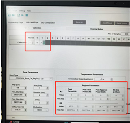
    2. Essentially to calculate this slope you need to gather the LCS impedance at various temperatures. To use the calibration sequence as a means to gather these data points you should alter the calibration sequence to include only burst 0 and 3. Then change the start and stop frequency of burst 3 to be that of the frequency you will use for temperature calibration (burst 5). This frequency should be far from resonance and have a generally flat response. You can then run this sequence with the LCS in a temp chamber and ULC1001 will calculate the LCS impedance. The impedance will populate in the region parameters section of the GUI. You then repeat this at various temperatures. 

    Regards,
    Sydney Northcutt

  • Thank you. Then, may I ask again, as you said, are these two bursts used for calibration? Then, does the obtained impedance value appear at the lower right corner of the picture

    Let me ask again. How to determine the resonant frequency of the LCS? Is it okay to set the starting frequency and the stopping frequency for burst 3 to be the same? Why is it necessary to ensure that the frequency set for burst 3 is far from the resonant frequency

  • I have a few more questions to ask

    For the six pulses used for calibration, are there any requirements for the starting and stopping frequency ranges? Which pulses are more suitable to be set to default values during calibration

    2. Will the frequency calibrated for the LCS change with the variation of impedance

  • Hello,

    Then, may I ask again, as you said, are these two bursts used for calibration? Then, does the obtained impedance value appear at the lower right corner of the picture

    Yes.

    How to determine the resonant frequency of the LCS?

    To know the resonance peaks of the LCS and essentially the overall impedance across frequency you will need an impedance analyzer of some sort. 

    Is it okay to set the starting frequency and the stopping frequency for burst 3 to be the same?

    Yes but this should only be done for calculating the slope.

    Why is it necessary to ensure that the frequency set for burst 3 is far from the resonant frequency

    This is because the frequency used for temperature calibration should be far from resonance. Burst 3 should only be set at this frequency and have the same start and stop frequency for calculating the temperature slope. In normal operation burst 3 should be around a resonance peak. 

    For the six pulses used for calibration, are there any requirements for the starting and stopping frequency ranges

    Yes. Do you have access to the full datasheet? If not please request access from the ULC1001 tool page. 

    Will the frequency calibrated for the LCS change with the variation of impedance

    The frequencies used for calibration are set by the user based on the impedance response of the LCS. 

    Regards,
    Sydney Northcutt

  • Hello, I'd like to ask a few more questions

    For ULC1001, can it be directly switched from the water removal mode to the deicing mode, or is it necessary to first enter the stop mode and then switch back to the deicing mode

    2. When calibrating ULC1001, is it necessary to ensure that the lens is clean? What impact will it cause if there are impurities on the lens

  • Hello,

    1. If a mode is running it should be terminated or finished before switching to another mode.

    2. Yes the lens should be clean when calibrating. When there is mass of the lens the impedance responses changes so if you calibrate the lens with contaminants on it you are calibrating based on that impedance response.

    Regards,
    Sydney Northcutt

  • Thank you. Then let me ask again

    1. For incorrect impurities, is there any relevant formula inside ULC1001 that can calculate the impedance value

    2. For the same set of calibration parameters, if the piezoelectric ceramic shows some attenuation after long-term operation, will the result after calibration still be fixed

    3. Based on your product experience, to what extent does piezoelectric ceramics deteriorate before their water removal effect becomes very poor

  • Hi,

    1. The impedance is calculated simply by Z = V / I. 

    2. If the piezos impedance response changes the corresponding calibration parameters will be different. 

    3. I do not have a comment on this one. It will be dependent on the unique piezo and LCS structure. I have not seen any piezo deteriorate in my experience but the water removal effect can become poor due improper assembly of the LCS. For example the lens becoming unglued from the piezo will result in poor cleaning performance.  

    Regards,
    Sydney Northcutt

  • Hello, I have a few questions to ask

    1. When measuring the impedance value of LCS in idle state and during normal operation, will there be any difference in the result? Also, will the impedance during water removal be different from that during ice removal

    2. On the GUI interface, can the piezoelectric ceramic be allowed to perform water removal operations while measuring impedance at this time

    3. You mentioned before that when measuring impedance, the parameters of pulse No. 3 need to be configured to be the same as those of Pulse No. 5. So, are all the parameters of Pulse No. 5 the default ones? I have tried here. If the starting frequency and ending frequency of Pulse No. 3 are changed, the obtained impedance value will change. Does that mean this value has no reference value?

  • Hello,

    1. The impedance response should be generally the same. Water and ice mode cleaning are mostly the same, just the ice mode has a heating bursts prior to the water cleaning sequence. Different frequencies are driven for water bursts and heating bursts.

    2. No, there is not any impedance calculations done during passive / cleaning bursts. This is only done in active blurts like calibration. 

    3. Burst 5 needs to use a frequency that is far from resonance which is dependent on your LCS. There is not a default / universal value to use here. You need to collect some impedance vs frequency data of your LCS to best determine this value. 
    Your measurements at burst 3 are just telling your LCS has different impedances at those frequencies. 

    Regards,
    Sydney Northcutt