This thread has been locked.

If you have a related question, please click the "Ask a related question" button in the top right corner. The newly created question will be automatically linked to this question.

DRV8244-Q1: Question about OCP operation in PWM mode

Part Number: DRV8244-Q1

Tool/software:

Hi.

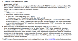
I have a question about the OCP operation of DRV8244-Q1.
In PWM mode, I am aware that the overcurrent protection is Hi-Z for both Out1 and Out2 as far as I read the datasheet, but am I wrong?

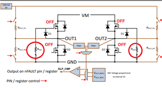
As part of my evaluation, I connected the Out1 and Out2 pins to the circuit in the image below and shorted them to the sink output circuit composed of FETs.

(LTspice is used to illustrate the circuit.)

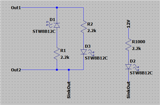
At this time, DRV8244-Q1 is operating with Out2 fixed at 12V, Out1 at 500Hz/50% of 12V, and the sink output at 12.5Hz/80% of 12V.

When the sink output was at GND level, an overcurrent occurred and DRV8244-Q1 stopped outputting. However, D1, which had been lit, began to blink at the same frequency as the sink output

if Out1 and Out2 were both Hi-Z, there would be no current path and no blinking should occur. Also, the MODE pin of DRV8244-Q1 has a 270kΩ pull-down.

Is there something I'm missing or misrecognizing?

Best regards.

Ryo

  • Hi 

    Thank you for your questions.

    Looks like you are not driving motor, but something R + diode + FET. It is difficult to expect the detaisl.

    However, 

    1) I recommend to read out Status 1/2/3. Then could know fault was detected by DRV.

    2) I do not have clear understanding what is your goal /expected behavior and how to drive external diode and resisters.

        If you capture waveforms, full schematic including external FET etc, I may be able to follow your question.

    regards

    Shinya

  • Sorry for the confusing question.
    Let me get what I'm asking, what is the definition of Hi-Z when protection works?

    To what is Hi-Z in relation to?
    Is it GND of the IC or between the OUT pins?

    The DRV8244-Q1 is using HW variant and PWM mode, DRVOFF and ITRIP are connected directly to GND.

  • Hi,

    thank you for your questions. 

    Definition of "HiZ" of output is 4 MOS FETs (HS/LS on OUT1/OUT2) are turned off.

    Strictly speaking, DRV8244-Q1 has internal resistance named "RHiZ", so OUTx is not true high impedance.

    In motor driver field, HiZ is used for meaning of all FETs are turned off.

    regards

    Shinya

  • Thank you for your response.
    I think I understand the reason for the strange behavior.

    I have an additional question, is it correct to recognize that R-HIZ is also ON when the protection is working?

    On p.15 of the datasheet, R-HIZ is described as “OUT resistance to GND in sleep or standby state”. I am thinking that even if the device is active and an overcurrent is activated, it will not go into standby or sleep state without some input instructions (1,1: PWM mode), is it correct to say that R-HIZ will be ON when the protection is activated regardless of these? (Since I can see the switch under the R-HIZ).

  • Hi,

    Thank you for your questions.

    When OCP is detected, device is still active state. However outputs are turned to HiZ (Both HS/LS FET OFF).

    regards

    Shinya 

  • Thank you for your answer.

    My question has been answered.

    Best regards.

    Ryo