Tool/software:
Hey everyone,
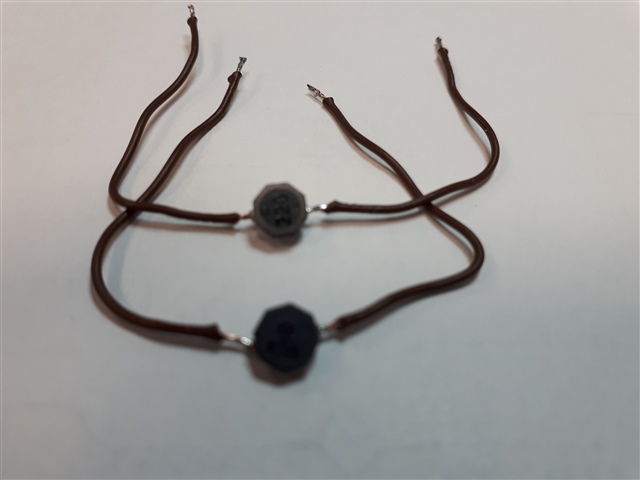
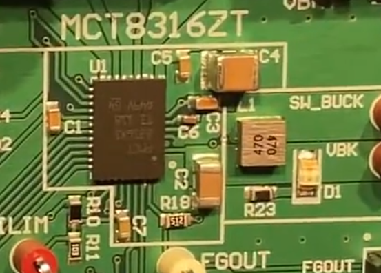
In our design we use the HW version of this driver to run the Faulhaber 2250S024BX4 with three (analog) Hall sensors. Having studied the datasheet and the MCT8316ZTEVM Evaluation Module documents thoroughly I am a bit puzzled how that shall be wired. But I had come up with the following design which works well and the motor spins smoothly:
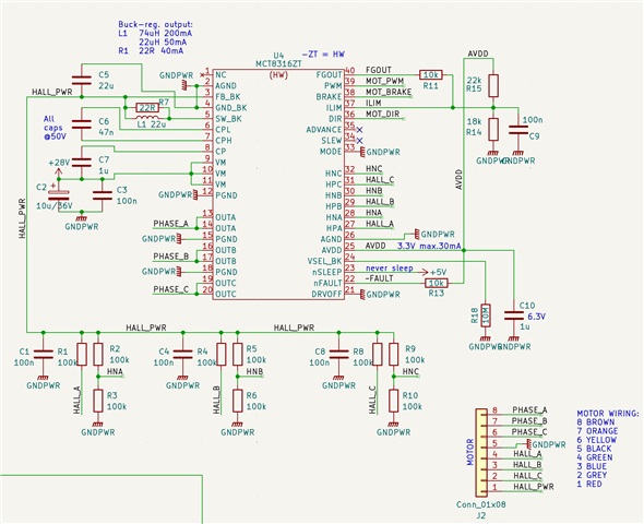
Even though the documents state the analog halls shall be without the pull-up resistors (R1, R4, R8), other combinations than this simply does not work. But this is not merit of my question.
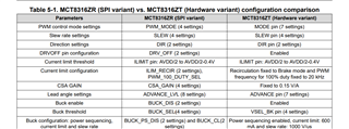
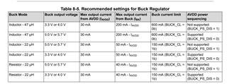
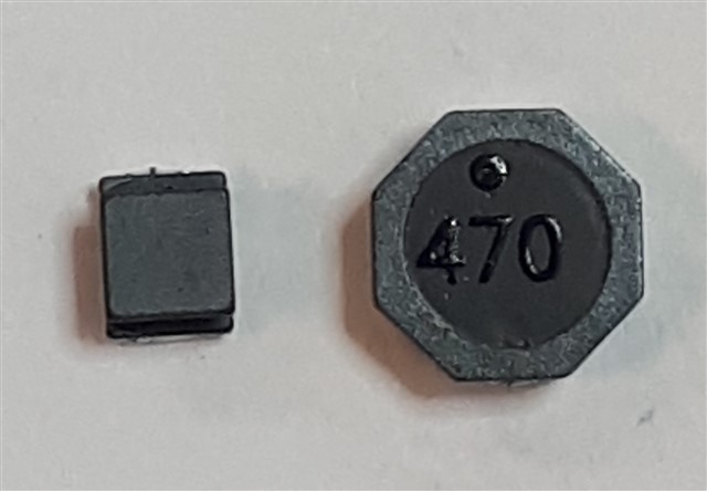
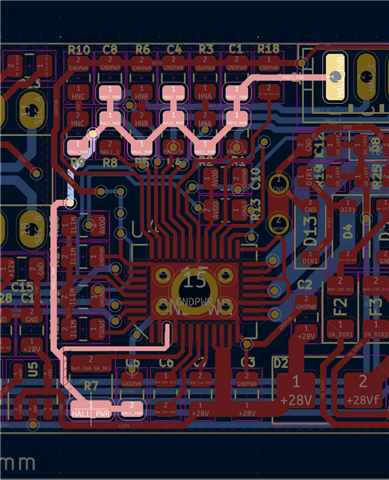
My problem is in the L1 (or R7) for the buck regulator. Again, based on the datasheet one of these (L1 or R7) MUST be populated even if the output of the buck regulator was not used [see the datasheet section 9.3.1.1.4 Using the Buck Regulator, page 85]. Originally I wanted to use other 3.3V source to power the hall sensors. Well, when it MUST be in there, why not to use it. It powers only the hall sensors as in the schema above, nothing else.
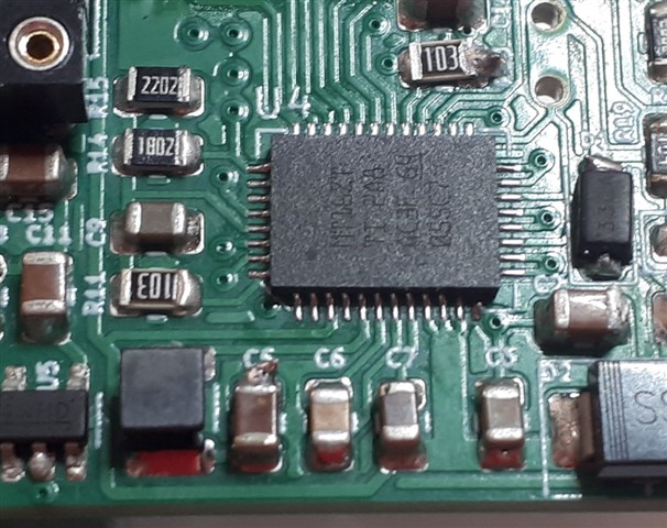
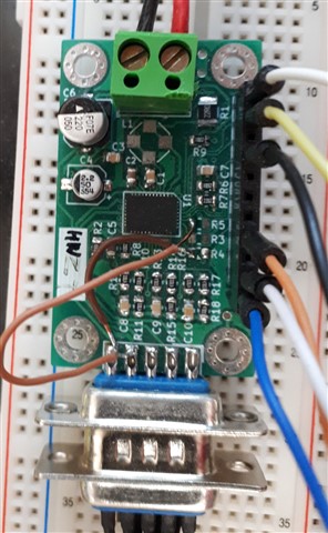
The trouble is that no matter if there is either it resistor or inductor, it produces immense amount of heat. After a while even when the motor does not spin there is above 70deg. C on that component while the current seems to also be heating the driver itself a bit (around 50 deg.C). When the motor spins freely (with zero load) the L1 reaches over 80 deg.C while this initiates problems in nearby components rated 'only' up-to 85deg.C. You can see the situation right here:
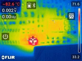
The red part is the inductor while the driver is the yellow-ish square at two o'clock from that position. The driver has approx 50deg.C in this particular situation.
What am I doing wrong? This cannot be normal behaviour, right? I have populated multiple boards and the problem is the same with all of them (meaning it is not a malfunctioning driver).
How can this be fixed?
Many thanks and endless gratitude for any help!
Josef