This thread has been locked.

If you have a related question, please click the "Ask a related question" button in the top right corner. The newly created question will be automatically linked to this question.

DRV8262: Noisy PWM signal

Part Number: DRV8262


Tool/software:

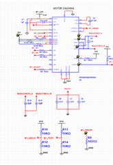
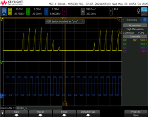
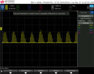
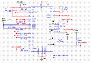
I designed a circuit to control a 48V motor using a PWM signal of 10Khz but I'm acquiring this noisy signal, how can I get a better signal ? 

  • Hi Octavio,

    Thank you for reaching out to us via this forum.

    Please describe what is the oscilloscope capture representing? Was it the OUT1,3 voltage or was it the load current? Per MODE1, 2 pins connected to 3V3 and OUTx connections the device configuration is single H-Bridge mode with PWM control. For PWM control the following scheme must be followed. When the motor is not driven both IN1 and IN2 must be a 1. To drive PWM input one of the inputs must remain a 1 and he other input must be PWM input. The bridge will be active while the PWM is in tOFF meaning PWM input 0 % would be 100 % output and vice versa. 

    Overall schematic looks okay. One missing item though, which happens to be an important element for output functionality. I do not see RIPROPI connected to the IPROPI1, 2 pins. If you do not require ITRIP based current regulation RIPROPI must be selected such that VIPROPI does not exceed VREF1, 2, here 3.3 V with the highest current peaks of the load. Without RIPROPI the IPROPIx output will saturate and force ITRIP to cut off the current - probably noisy output. 

    For further analysis please capture IN1, 2 and OUT 1-3 and 2-4 voltage waveforms as well as a second capture with IN1, 2, the active PWM output depending on direction and the load current waveform using a current probe. Thank you.

    Regards, Murugavel  

  • Hi Murugavel, this is the circuit with the missed items, I replaced R9 with 0 Ohms resistor to make sure it does not exceed VRef 

    Here is another plot with IN1 and IN2(green and blue lines) and OUT1-3 and OUT2-4(I used a differential probe), at the moment  I don't have a current probe.

  • Hi Octavio,

    Thanks for sharing the additional items. 

    I replaced R9 with 0 Ohms resistor to make sure it does not exceed VRef 

    Thanks. This will eliminate this one variable from the list.

    Here is another plot with IN1 and IN2(green and blue lines) and OUT1-3 and OUT2-4(I used a differential probe), at the moment  I don't have a current probe.

    Was this behavior repeatable with more than one board? Was the power supply stable a capture of VM during this time would reveal if there was an issue. If you happen to have a 10 to 100 mΩ shunt resistor you can connect this in series with the motor and measure the voltage across it with a diff probe for current. What was the status of nFAULT during PWM drive? Can we confirm with the oscilloscope it was stable logic high? 

    Also please capture OUT1,3 and OUT2,4 separately instead of the differential voltage between them.  

    The DECAY and TOFF pins have resistor dividers - snippet below. This is not the suggested control for these pins.

    Below suggestion for DECAY pin. For BDC motors slow decay is recommended.

    Below suggestion for TOFF. You could use the longest time 32 μs or 24 μs. These two settings don't matter while current regulation is disabled with IPROPIx connected to GND. 

    Thank you.

    Regards, Murugavel