Tool/software:
I am driving a bidirectional DC motor using drv8874.
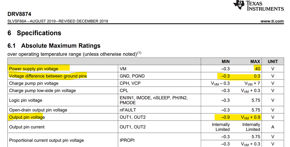
The operating voltage is 28V, and the motor consumes 400mA of current when not loaded.
The motor driver was damaged during operation. (The temperature rose over 100 degrees, and it did not burn due to the current limit of the power supply.)
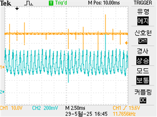
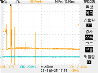
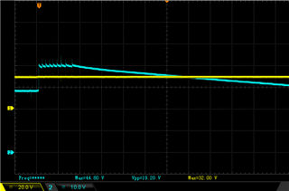
BEMF occurred over 60V for 250us.
There was no problem when driving a 1A resistive load and a 300mA solenoid valve.
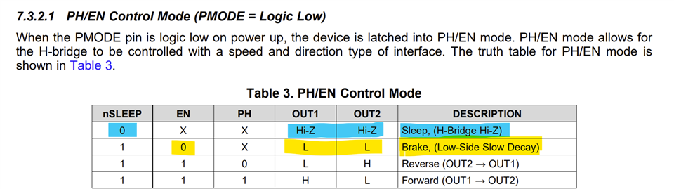
The data sheet says that when enable is input low, it can enter brake mode to reduce the counter electromotive force, but it seems insufficient.
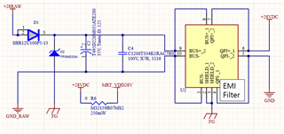
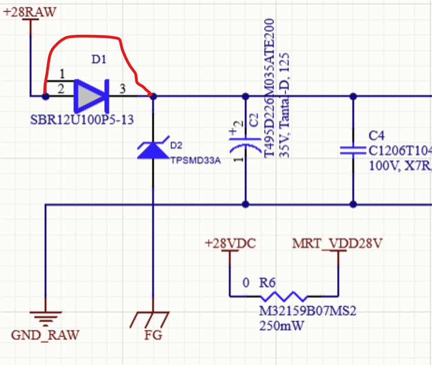
I also installed a 100uF electrolytic capacitor and a 100nF ceramic capacitor on the VM side.
When I searched the community, it said to install a TVS diode on both ends of the motor or increase the bulk capacitor capacity, but I am in an environment where I cannot increase it any further.
Please suggest a good solution. Please recommend an appropriate motor driver, TVS diode, Schottky diode, etc. Thank you for reading.