I hvae run the bldc_sensorless for the seven levels follow by the DRV8312-C2-KIT,and everything is ok,but when I what to get to know the detail how it works,I found some difficults in the code。
first of all:
1.we use the “pu” to let speed,pid control in -1~1.and we can formulate the pu in to r/min by:
v.Speed = _IQdiv(v.SpeedScaler,v.EventPeriod);
v.SpeedRpm = _IQmpy(v.BaseRpm,v.Speed);
But I was confuse by the definition,such as
speed1.BaseRpm = 120*(BASE_FREQ/POLES);
speed1.SpeedScaler = (Uint32)(ISR_FREQUENCY/(1*BASE_FREQ*0.001));
how it comes from?What does it mean?
What I know only is:
// Define the base quantites 基值 用于设置标幺话的基值用
#define BASE_VOLTAGE 66.32 // Base peak phase voltage (volt), maximum measurable DC Bus/sqrt(3)
#define BASE_CURRENT 5 // Base peak phase current (amp) , maximum measurable peak current
#define BASE_FREQ 200 // Base electrical frequency (Hz)
#define MAX_RPM 3000 // max RMP
// Define the ISR frequency (kHz)
#define ISR_FREQUENCY 40
#define PWM_FREQUENCY 20
2.Something about PID:
pid1_idc.param.Kp = _IQ(3.176*BASE_CURRENT/BASE_VOLTAGE);
pid1_idc.param.Kr = _IQ(1.0);
pid1_idc.param.Ki = _IQ(T/0.0005);
In the code we just use PI control ,3.176*BASE_CURRENT/BASE_VOLTAGE,what does it means?how can I adjust by my self?Is this have some matter with “pu”?
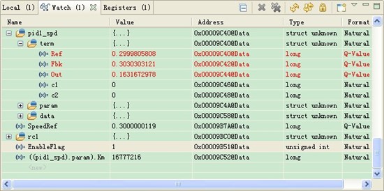
3.please help me to point out where I error:
the source code in BLDC_sensorless to let the PID to control PWM is :(1061)
pwm1.DutyFunc = (int16)_IQtoQ15(pid1_spd.term.Out); // controlled Speed duty-cycle
the code just use the pid.out to control the PWM ,but what I think is:
pwm1.DutyFunc = pwm1.DutyFunc + (int16)_IQtoQ15(pid1_spd.term.Out);
4. cmtn1.Va = _IQ15toIQ((AdcResult.ADCRESULT4<<3)-BemfA_offset);
cmtn1.Vb = _IQ15toIQ((AdcResult.ADCRESULT5<<3)-BemfB_offset);
cmtn1.Vc = _IQ15toIQ((AdcResult.ADCRESULT6<<3)-BemfC_offset);
I know that AdcResult.ADCRESULTx is the result we want in ADC. It can be 0~0xfff,am I right?but why ADCRESULTx shifts 3 can turn out tobe IQ15?I think it is IQ3....
5.Someting about ADC sample
As in F2803XILEG_VDC_BLDC.h discrible, I guess the ADC sample frequency in every channel is 10K / Channel.
In my view about round-robin means that all the DAC sample is trigger by SOC0,but once to trigger a channel to sample.Once at a time ,all the channel is trigger on EPWM1A.So SOC0 interrupt have the same fequency with PWM,but every channel's sample fequency is PWM's / Channel ,am I right?
Thanks for help