Other Parts Discussed in Thread: DRV8434A, DRV8434S, DRV8711
Tool/software:
I'm using DRV8434AEVM to protype a setup togerhter with a STM32 eval board and a small stepper motor for a V8 idle air control. Stepping at 330Hz. No Learning mode completed yet.
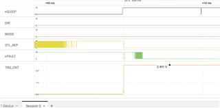
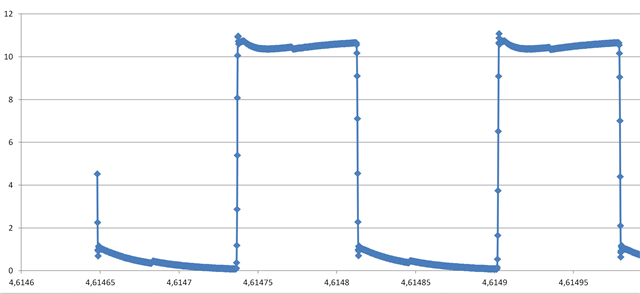
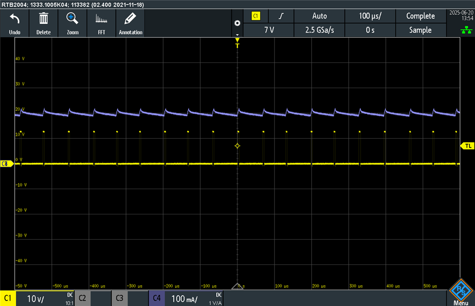
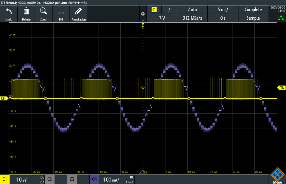
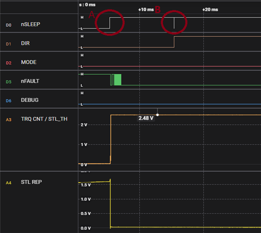
After initial STM board setup I set nSLEEP and ENABLE=1, and MODE=0. This results in STL_REP=0, nFAULT=1. TRQ_CNT=2,5V. If I then start to step motor away from end position, TRQ_CNT drops to 0V after 8 steps. When I later hit the end position STL_REP=1, nFAULT=0, but TRQ_CNT is unchanged at 0V.
Is this normal?
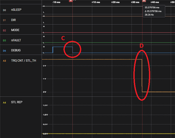
Becuase then I change direction, switch to Learning mode, and go back to end position. Same thing again. When end position is hit STL_REP=1, nFAULT=0, and TRQ_CNT is unchanged at 0V. But STL_REP will not change bacl to 0 if I continue to step towards end position. So it seems like learning failed.
But DRV8434A obviously seems to detect that end position is found since STL_REP changes immediately when end pos is hit, But it seems like the Torque Count value is so low that it won't show.
Any suggestion on how to get learning to work?