This thread has been locked.

If you have a related question, please click the "Ask a related question" button in the top right corner. The newly created question will be automatically linked to this question.

ULC1001-DRV290XEVM: output signal of the driver

Part Number: ULC1001-DRV290XEVM
Other Parts Discussed in Thread: ULC1001, ULC1001-DRV2911EVM

Tool/software:

Dear TI representative,

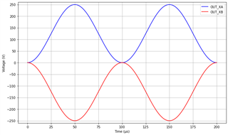
I am currently working with the ULC1001-DRV290XEVM, but I am not entirely certain how to interpret the output signal. The board indicates an output of 0–250 Vp. In the accompanying software, it is possible to set the “Amp puV” parameter. I assume that setting this value to 1 results in a 250 V peak differential signal between OUT_XA and OUT_XB. However, I would like to confirm: does this mean one output reaches +250 Vp and the other –250 Vp, creating a total differential of 500 Vp, or is the signal +125 Vp on one output and –125 Vp on the other, creating a total differential of 250 Vp? Another question, does the signal swing symmetrically around ground between the two outputs, or does one output remain at 0 Vp while the other reaches 250 Vp?

This information is important for my application, as I am using a piezo ring from Thorlabs (model PA44M3KW), which requires one side to be grounded. Would you consider it safe and appropriate to drive this piezo ring using the ULC1001-DRV290XEVM?

Thank you in advance for your time and support. If any part of my question requires clarification, I would be happy to elaborate.

Kind regards,
Hidde van de Rijke

  • Hidde,

    250Vp is the maximum voltage it can support and its output reaches +250 Vp and the other –250 Vp. When Amp puV = 1, it doesn't necessarily mean the output will be 250Vp. The output voltage is also determined by load. 

    In the EVM, the ULC1001 is the DSP and send the PWM signal to the DRV290X driver. The output of the DRV290X driver can support up 50Vp. The low pass LC filter at the driver output can not only filter the high freq signals, but also can provide the voltage gain so that the maximum voltage can be as high as 250V. 

    The issue is that the DRV290X driver can support up to 200kHz, while the model PA44M3KW seems operate at 260kHz based on its data sheet (unless you use the piezo's low freq mode). The vibration will be weak. 

  • Dear Hailong Chen,
    Thank you for your response.
    I am primarily interested in setting specific output voltages. Besides measuring the voltage with an oscilloscope, is there a way to theoretically determine the output voltage? For instance, if the impedance of the connected piezo ring is known, can the voltage be calculated based on the Amp puV setting? Many suppliers of piezo rings specify a maximum tolerable voltage, so being able to set the output accurately is quite important.
    Additionally, I was advised to use lower frequencies, so I was not planning on operating above 200 kHz. However, the driver states a supported frequency range of 40–400 kHz, while you mentioned that operation above 200 kHz is not supported. Could you clarify this discrepancy? I have also used frequencies below 40 kHz continuously with another piezo ring, which appeared to work without any issue.
    Thank you in advance for your time and support. I look forward to hearing from you.
  • The voltage across the piezo can only be estimated based on the resonant frequency of the piezo, rather than accurately calculated. The reason is that this EVM uses a LC filter as the voltage gain. The voltage gain is dependent on the piezo load as well. 

    Regarding the supported frequency, you are right. The ULC1001-DRV290XEVM can support to 400kHz. We have another similar EVM ULC1001-DRV2911EVM can only support up to 200kHz. 

  • I would like to confirm that I correctly understand the appearance of the output signal. For reference, I have created an image of the output showing the signal at maximum voltage and a frequency of 10 kHz. If the actual output differs, please describe its characteristics or provide a graph that accurately represents it. I hope my image is sufficiently clear, if not, please let me know.

  • That's great to hear. So, just to confirm, does this mean that the maximum output voltage the driver can reach is 500 Vpp? As you mentioned earlier, the output voltage is not exactly proportional to the "amp puv" setting. If I’m using a piezo ring with a maximum voltage rating of 150 Vpp and I want to achieve maximum displacement, would you recommend setting the "amp puv" to 0.3 (150/500)? Or would you suggest a different approach?

  • This EVM is designed specifically for driving the lens cleaning module, not to drive a universal piezo.  The voltage applied across the piezo is very dependent on the piezo load itself. With the current LC filter configuration on the board, it may not be able to output a 150V for your piezo whatever your amp puv is.