This thread has been locked.

If you have a related question, please click the "Ask a related question" button in the top right corner. The newly created question will be automatically linked to this question.

DRV8428: schematic check

Part Number: DRV8428

Tool/software:

Hi

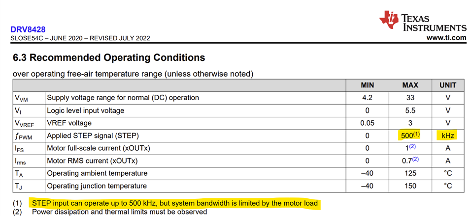
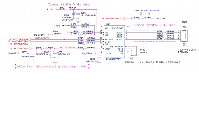
The customer uses DRV8428, but the stepper motor does not move. The driver output has a waveform AOUT 2 phase delay AOUT 1 180 degrees, BOUT 1 delay AOUT 2 90 degrees, BOUT 2 delay BOUT 1 180 degrees, the motor output frequency is 500 mHz VREF is currently 1.8V The hardware settings are as follows, the motor specification is attached, the software can only control STEP and VREF, please help to check the schematic  to see if there is any setting error

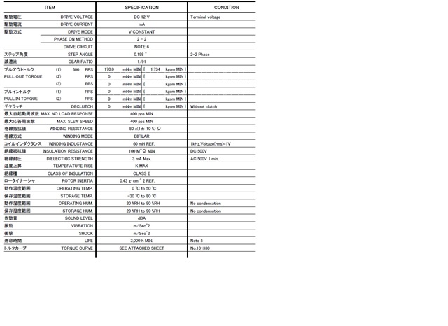
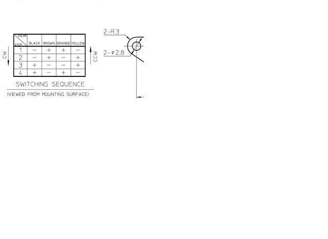
The motor specification defines the rotation timing. How should the 8428 be defined to meet this requirement?

  • Hi Gareth,

    Thanks for your question. Let me review the information and get back to you.

    Regards, Murugavel 

  • Hi Gareth,

    Overall, the schematic looks okay. VREF is 1.8 V which means IFS = 1.8 / 3 = 600 mA. The motor specifications is not showing the current mA, but calculating from its winding resistance and voltage specs it would be 12/80 = 150 mA. 

    Based on the schematic VM = 12 V. Because of the winding resistance the current can never go higher than 150 mA (12/80). So VREF = 1.8 V would not result in chopping current regulation. VREF must be set < 0.45 V or VM must be increased to accommodate VM/R > 150 mA. The inductance of the motor is also pretty high so it can support very slow speeds only.

     M0 and M1 = logic 1, this sets driver in 1/8 step mode and decay  = logic 0 for STRC decay mode. 

    That all said, assuming 3V3-STBY rail is 3.3 V and VREF is active I expect the motor to spin. Please double check the winding connections. Could you please share the coil A and coil B current waveforms while STEP input applied, using a current probe for debug? Can you also verify if DVDD output is 5 V? Thank you.

    Regards, Murugavel  

  • Hi Murugavel  

    Thanks for your analysis

    At present, it is known that the output of my IC Bout 1 Bout 2 pin is misaligned, and the order of the motor line is reversed. After correction, the driver output timing has been consistent with the motor rotation timing. I can hear the sound of the motor moving (but I can't see it moving). I will adjust the STEP again when our software is available.

  • Hi Gareth,

    Sounds good. Thanks for the update.

    Regards, Murugavel 

  • Hi Murugavel  

    After the correction, the motor can now rotate, but the rotation speed is not as expected. Is there any way to speed up the rotation? Currently we are set to Mode 0 0 - 100% full step

  • Hi Gareth,

    The speed of rotation of the stepper motor is defined by the step rate and its speed vs. torque characteristics. The below specifications for the motor was given for 300 PPS at full-step mode. If there is sufficient torque to drive the load at higher PPS you can try increasing the STEP input frequency. Beyond a certain point the motor cannot produce enough torque and will stall. That would be a limitation of the motor.

    To get further usable speed out of this motor the supply voltage must be increased to 24 V for example. The current will be regulated to the current set by the Vref regardless of the VM input voltage. Thank you. 

    Regards, Murugavel 

  • Hi Murugavel  

    If the stepper motor model remains unchanged and its maximum PPS and step angle are fixed, can the motor speed be increased by replacing a different driver IC?

  • Hi Gareth,

    The limitation is because of the stepper motor characteristics, not from the driver. The DRV8428 is capable of driving higher PPS, for example 100 kPPS. Its fSTEP specification is up to 500 kHz, most motors cannot keep up with this PPS hence it is mentioned as bandwidth limited by motor load.   

    If the stepper motor model remains unchanged and its maximum PPS and step angle are fixed, can the motor speed be increased by replacing a different driver IC?

    If the VM voltage is unchanged, the answer to this question is no it cannot be increased. If you increase the VM to 24 V from 12 V, the same driver can give you additional speed increase. You could use a driver such as the DRV8452PWP and use VM = 48 V to get even higher maximum speed. All these drivers are constant current drivers. So the current driven through the coil will not change regardless of the VM votlage. The reason why VM = 12 V has lower speed limit is at high STEP PPS the current through the inductor will not reach the target current within that STEP period. Thank you.

    Regards, Murugavel