Hello,
I'm working with two DRV8904-Q1 devices in a daisy chain configuration and I'm trying to fully understand the SPI response format, particularly during write operations.
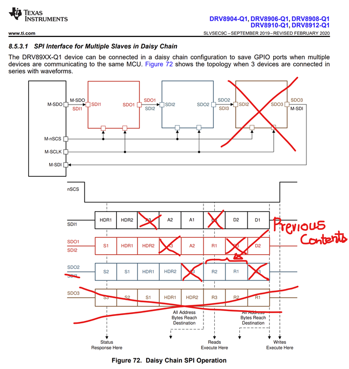
According to section 8.5.3.1 of the datasheet, the SPI response after a write command should include:
- 2 bytes of status (one per device, in reverse order),
- 2 bytes echoing the header,
- 2 bytes containing the previous content of the register that was written.
However, in my tests, the last 2 bytes of the response always match the register address I just wrote to, not the previous content of that register. For example, when writing to register 0x07, I consistently receive 0x07 0x07 in the last two bytes of the response, regardless of what value I write.
I also tested with register 0x1F and received 0x1F 0x1F, which further suggests that the response contains the address, not the previous value.
Could you please clarify:
- What exactly is returned in the last 2 bytes of the SPI response after a write command in daisy chain mode?
- Is the datasheet incorrect or incomplete in this regard?
Thank you in advance for your help!
Best regards,
Paolo Coita
Signal s.r.l. - Italy