Tool/software:
Hi,
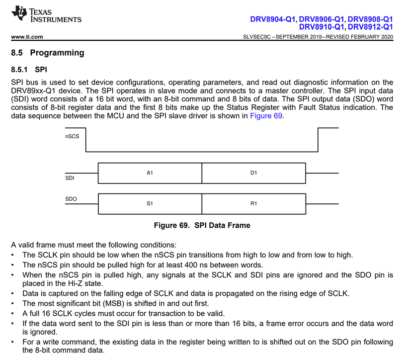
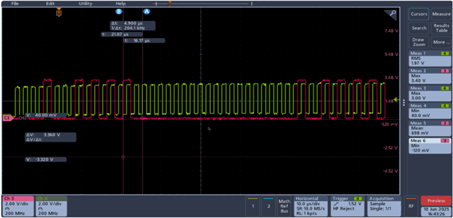
I am using DRV8912 in parallel configuration (4 half bridges connected parallelly) and planning to operate them in continuous mode. The configuration settings for Control register1 using SDI are 0x08AA and for control register2 using SDI in 0x0955.Is it okay if I send both the Datas in same clock frame (as shown in figure below) or should I generate different clock frames of 16bit each for data transfer to happen. Also, could you please confirm if these settings are enough for the motor drive to operate in forward direction using continuous mode.
Regards,
Reshma