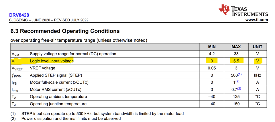
Tool/software:
We are using a DRV8428RTER on a simple board to drive a small step bipolar motor (winding res: 60ohm) at 12V supply.
Unfortunately we can't get any output to drive the motor windings.
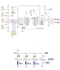
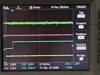
We have tied nSLEEP to VM: we get stable DVDD as expected. (img. 1).
M0, M1 and Decay mode are set to GND (tried also connected to DVDD); VREF is obtained from DVDD with a 33k/3k3 partition to get 0.55V (so plenty of current for these windings).
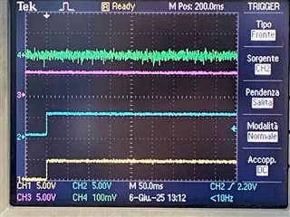
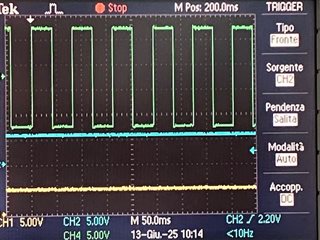
We tried, then, to rise ENable after some seconds. We connected EN trhough a 220k resistor and a 22p cap, to use nFAULT as indicated in Fig 7-15. Rising the EN resulted also in nFAULT to rise, stable.
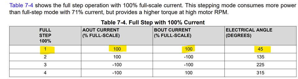
Am I right to expect that both windings should be, at this moment, active with, in this configuration, 100% current? We see no variation at the terminals of windings. (see img. 2)
Trying to pulse STEP doesn't change anything.
Capacitors on VM: 100uF + 10nF / DVDD 470n
Can't see what we're doing wrongly...
Img.1 : Ch1 VM ; Ch2 DVDD
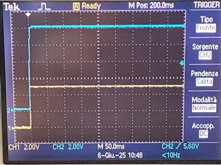
img 2: Ch1: yellow nFAULT; Ch2 blue ENable; Ch3 pink DVDD; Ch 4 green voltage across A+/A- (channels are insulated)